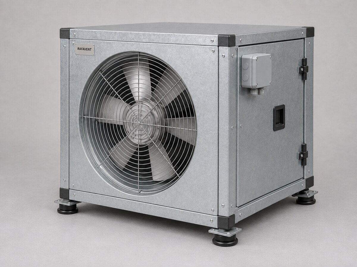
RAFAVENT AXIAL FAN SUBFAMILY
High-Duty Boxed Axial Fans
Packaged axial fan modules integrated into rigid protective or acoustic enclosures for high-duty supply and extract applications.
Documentation workspace← Back to Industrial Axial Fans
RAFAVENT RF-HDB SERIES
High-Duty Boxed Axial Fans — Technical Selection Data
Direct-drive axial fan modules packaged inside rigid steel enclosures for protected, serviceable or acoustically treated supply and extract duty.
RAFAVENT Engineering Calculation — Preliminary Selection — Non-Certified. Values are calculated at standard air density 1.20 kg/m³ and are not laboratory-certified ratings. Airflow, shut-off pressure and sound figures are not simultaneous guarantees. Final selection requires the project duty point, system-effect review and approved production drawing.
Construction and application
- Galvanized or painted double-skin steel enclosure with removable service panels; acoustic infill, weather protection and base frame are project options.
- Internal direct-drive tubular axial fan module with aluminium impeller; production balancing and vibration acceptance required before dispatch.
- Flexible internal connections, anti-vibration mounts, guards, access doors and external terminal box are configured by project.
- Normal clean-air duty basis −20 to +50 °C. No smoke, ATEX, marine or high-temperature certification is claimed for this preliminary series.
Model selection table
Recommended Q and Ps describe the intended selection envelope and are not opposite corners of a guaranteed operating point. Estimated free-field A-weighted sound pressure at 3 m has ±6 dB(A) uncertainty and represents the internal fan-module baseline before enclosure attenuation, duct reflection, guards and system effects. Final box envelope, mass, insertion loss and external duty require project-specific calculation.
Calculated model curves
Open a model to view its six-point preliminary Q–Ps curve. Curves represent the internal fan module; enclosure components and connections add resistance that must be included in final unit selection.
RF-HDB-250 — calculated Q–Ps curve
Airflow Q (m³/h)Static pressure Ps (Pa)
| Point | Q (m³/h) | Ps (Pa) |
|---|
| 1 | 0 | 162 |
| 2 | 215 | 157 |
| 3 | 429 | 143 |
| 4 | 644 | 113 |
| 5 | 859 | 70 |
| 6 | 1,073 | 0 |
RF-HDB-280 — calculated Q–Ps curve
Airflow Q (m³/h)Static pressure Ps (Pa)
| Point | Q (m³/h) | Ps (Pa) |
|---|
| 1 | 0 | 203 |
| 2 | 302 | 197 |
| 3 | 603 | 179 |
| 4 | 905 | 142 |
| 5 | 1,206 | 87 |
| 6 | 1,508 | 0 |
RF-HDB-315 — calculated Q–Ps curve
Airflow Q (m³/h)Static pressure Ps (Pa)
| Point | Q (m³/h) | Ps (Pa) |
|---|
| 1 | 0 | 257 |
| 2 | 429 | 250 |
| 3 | 859 | 226 |
| 4 | 1,288 | 180 |
| 5 | 1,718 | 111 |
| 6 | 2,147 | 0 |
RF-HDB-355 — calculated Q–Ps curve
Airflow Q (m³/h)Static pressure Ps (Pa)
| Point | Q (m³/h) | Ps (Pa) |
|---|
| 1 | 0 | 327 |
| 2 | 615 | 317 |
| 3 | 1,229 | 288 |
| 4 | 1,844 | 229 |
| 5 | 2,459 | 141 |
| 6 | 3,073 | 0 |
RF-HDB-400 — calculated Q–Ps curve
Airflow Q (m³/h)Static pressure Ps (Pa)
| Point | Q (m³/h) | Ps (Pa) |
|---|
| 1 | 0 | 415 |
| 2 | 879 | 403 |
| 3 | 1,759 | 365 |
| 4 | 2,638 | 291 |
| 5 | 3,517 | 178 |
| 6 | 4,396 | 0 |
RF-HDB-450 — calculated Q–Ps curve
Airflow Q (m³/h)Static pressure Ps (Pa)
| Point | Q (m³/h) | Ps (Pa) |
|---|
| 1 | 0 | 525 |
| 2 | 1,252 | 509 |
| 3 | 2,504 | 462 |
| 4 | 3,756 | 368 |
| 5 | 5,008 | 226 |
| 6 | 6,260 | 0 |
RF-HDB-500 — calculated Q–Ps curve
Airflow Q (m³/h)Static pressure Ps (Pa)
| Point | Q (m³/h) | Ps (Pa) |
|---|
| 1 | 0 | 648 |
| 2 | 1,717 | 629 |
| 3 | 3,435 | 571 |
| 4 | 5,152 | 454 |
| 5 | 6,869 | 279 |
| 6 | 8,587 | 0 |
RF-HDB-560 — calculated Q–Ps curve
Airflow Q (m³/h)Static pressure Ps (Pa)
| Point | Q (m³/h) | Ps (Pa) |
|---|
| 1 | 0 | 357 |
| 2 | 1,597 | 346 |
| 3 | 3,195 | 314 |
| 4 | 4,792 | 250 |
| 5 | 6,389 | 153 |
| 6 | 7,987 | 0 |
RF-HDB-630 — calculated Q–Ps curve
Airflow Q (m³/h)Static pressure Ps (Pa)
| Point | Q (m³/h) | Ps (Pa) |
|---|
| 1 | 0 | 451 |
| 2 | 2,274 | 438 |
| 3 | 4,549 | 397 |
| 4 | 6,823 | 316 |
| 5 | 9,098 | 194 |
| 6 | 11,372 | 0 |
RF-HDB-710 — calculated Q–Ps curve
Airflow Q (m³/h)Static pressure Ps (Pa)
| Point | Q (m³/h) | Ps (Pa) |
|---|
| 1 | 0 | 573 |
| 2 | 3,255 | 556 |
| 3 | 6,511 | 504 |
| 4 | 9,766 | 401 |
| 5 | 13,022 | 246 |
| 6 | 16,277 | 0 |
RF-HDB-800 — calculated Q–Ps curve
Airflow Q (m³/h)Static pressure Ps (Pa)
| Point | Q (m³/h) | Ps (Pa) |
|---|
| 1 | 0 | 409 |
| 2 | 3,493 | 397 |
| 3 | 6,986 | 360 |
| 4 | 10,478 | 287 |
| 5 | 13,971 | 176 |
| 6 | 17,464 | 0 |
RF-HDB-900 — calculated Q–Ps curve
Airflow Q (m³/h)Static pressure Ps (Pa)
| Point | Q (m³/h) | Ps (Pa) |
|---|
| 1 | 0 | 518 |
| 2 | 4,973 | 502 |
| 3 | 9,946 | 456 |
| 4 | 14,919 | 363 |
| 5 | 19,893 | 223 |
| 6 | 24,866 | 0 |
RF-HDB-1000 — calculated Q–Ps curve
Airflow Q (m³/h)Static pressure Ps (Pa)
| Point | Q (m³/h) | Ps (Pa) |
|---|
| 1 | 0 | 640 |
| 2 | 6,822 | 620 |
| 3 | 13,644 | 563 |
| 4 | 20,466 | 448 |
| 5 | 27,287 | 275 |
| 6 | 34,109 | 0 |
Selection requirements
Confirm airflow, total static pressure, duct diameter, installation orientation, straight inlet/outlet conditions, voltage and phase, control method, temperature, corrosion class, permissible sound level and accessories before order.
Technical documents, dimensions and service
Technical documents and dimensions
Final dimensions, connection details, materials, motor data and project drawings are issued for the selected configuration after engineering review.
Installation and maintenance
Provide level support, flexible connections, guarded drive components, alignment checks and safe maintenance access. Follow the approved project-specific O&M document.
Selection tables and calculated curves on this page are preliminary engineering guidance, not certified RAFAVENT test ratings. Confirm the operating point and controlled documents before order.