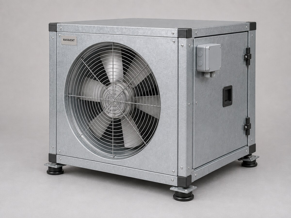
High-Duty Boxed Axial Fans — Technical Selection Data
Direct-drive axial fan modules packaged inside rigid steel enclosures for protected, serviceable or acoustically treated supply and extract duty.
RAFAVENT Engineering Calculation — Preliminary Selection — Non-Certified. Values are calculated at standard air density 1.20 kg/m³ and are not laboratory-certified ratings. Airflow, shut-off pressure and sound figures are not simultaneous guarantees. Final selection requires the project duty point, system-effect review and approved production drawing.
Construction and application
Galvanized or painted double-skin steel enclosure with removable service panels; acoustic infill, weather protection and base frame are project options.
Internal direct-drive tubular axial fan module with aluminium impeller; production balancing and vibration acceptance required before dispatch.
Flexible internal connections, anti-vibration mounts, guards, access doors and external terminal box are configured by project.
Normal clean-air duty basis −20 to +50 °C. No smoke, ATEX, marine or high-temperature certification is claimed for this preliminary series.
Model selection table
Model
Ø mm
rpm
Recommended Q m³/h
Recommended Ps Pa
Max free-air Q
Shut-off Ps
Preliminary motor selection kW
Supply
Est. LpA @3m dB(A)
Approx. internal fan module Ø × L S/L mm
Est. kg
RF-HDB-250
250
1450
515–859
70–133
1,073
162
0.12
230 V 1Ph / 400 V 3Ph
48 ±6
Ø300 × 368 / 508
10
RF-HDB-280
280
1450
724–1,206
87–167
1,508
203
0.12
230 V 1Ph / 400 V 3Ph
51 ±6
Ø330 × 390 / 542
10
RF-HDB-315
315
1450
1,031–1,718
111–211
2,147
257
0.12
230 V 1Ph / 400 V 3Ph
54 ±6
Ø365 × 416 / 582
11
RF-HDB-355
355
1450
1,475–2,459
141–268
3,073
327
0.25
230 V 1Ph / 400 V 3Ph
57 ±6
Ø405 × 446 / 628
15
RF-HDB-400
400
1450
2,110–3,517
178–340
4,396
415
0.55
230 V 1Ph / 400 V 3Ph
60 ±6
Ø450 × 480 / 680
19
RF-HDB-450
450
1450
3,005–5,008
226–431
6,260
525
0.75
230 V 1Ph / 400 V 3Ph
63 ±6
Ø500 × 518 / 738
23
RF-HDB-500
500
1450
4,122–6,869
279–532
8,587
648
1.5
230 V 1Ph / 400 V 3Ph
66 ±6
Ø550 × 555 / 795
29
RF-HDB-560
560
960
3,834–6,389
153–292
7,987
357
0.75
230 V 1Ph / 400 V 3Ph
60 ±6
Ø610 × 600 / 864
36
RF-HDB-630
630
960
5,459–9,098
194–370
11,372
451
1.1
230 V 1Ph / 400 V 3Ph
63 ±6
Ø680 × 652 / 944
44
RF-HDB-710
710
960
7,813–13,022
246–470
16,277
573
2.2
230 V 1Ph / 400 V 3Ph
66 ±6
Ø760 × 712 / 1036
56
RF-HDB-800
800
720
8,383–13,971
176–336
17,464
409
1.5
230 V 1Ph / 400 V 3Ph
63 ±6
Ø850 × 780 / 1140
69
RF-HDB-900
900
720
11,936–19,893
223–425
24,866
518
3
400 V 3Ph
66 ±6
Ø950 × 855 / 1255
86
RF-HDB-1000
1000
720
16,372–27,287
275–524
34,109
640
5.5
400 V 3Ph
69 ±6
Ø1050 × 930 / 1370
105
Recommended Q and Ps describe the intended selection envelope and are not opposite corners of a guaranteed operating point. Estimated free-field A-weighted sound pressure at 3 m has ±6 dB(A) uncertainty and represents the internal fan-module baseline before enclosure attenuation, duct reflection, guards and system effects. Final box envelope, mass, insertion loss and external duty require project-specific calculation.
Calculated model curves
Open a model to view its six-point preliminary Q–Ps curve. Curves represent the internal fan module; enclosure components and connections add resistance that must be included in final unit selection.
RF-HDB-250 — calculated Q–Ps curve
Point
Q (m³/h)
Ps (Pa)
1
0
162
2
215
157
3
429
143
4
644
113
5
859
70
6
1,073
0
RF-HDB-280 — calculated Q–Ps curve
Point
Q (m³/h)
Ps (Pa)
1
0
203
2
302
197
3
603
179
4
905
142
5
1,206
87
6
1,508
0
RF-HDB-315 — calculated Q–Ps curve
Point
Q (m³/h)
Ps (Pa)
1
0
257
2
429
250
3
859
226
4
1,288
180
5
1,718
111
6
2,147
0
RF-HDB-355 — calculated Q–Ps curve
Point
Q (m³/h)
Ps (Pa)
1
0
327
2
615
317
3
1,229
288
4
1,844
229
5
2,459
141
6
3,073
0
RF-HDB-400 — calculated Q–Ps curve
Point
Q (m³/h)
Ps (Pa)
1
0
415
2
879
403
3
1,759
365
4
2,638
291
5
3,517
178
6
4,396
0
RF-HDB-450 — calculated Q–Ps curve
Point
Q (m³/h)
Ps (Pa)
1
0
525
2
1,252
509
3
2,504
462
4
3,756
368
5
5,008
226
6
6,260
0
RF-HDB-500 — calculated Q–Ps curve
Point
Q (m³/h)
Ps (Pa)
1
0
648
2
1,717
629
3
3,435
571
4
5,152
454
5
6,869
279
6
8,587
0
RF-HDB-560 — calculated Q–Ps curve
Point
Q (m³/h)
Ps (Pa)
1
0
357
2
1,597
346
3
3,195
314
4
4,792
250
5
6,389
153
6
7,987
0
RF-HDB-630 — calculated Q–Ps curve
Point
Q (m³/h)
Ps (Pa)
1
0
451
2
2,274
438
3
4,549
397
4
6,823
316
5
9,098
194
6
11,372
0
RF-HDB-710 — calculated Q–Ps curve
Point
Q (m³/h)
Ps (Pa)
1
0
573
2
3,255
556
3
6,511
504
4
9,766
401
5
13,022
246
6
16,277
0
RF-HDB-800 — calculated Q–Ps curve
Point
Q (m³/h)
Ps (Pa)
1
0
409
2
3,493
397
3
6,986
360
4
10,478
287
5
13,971
176
6
17,464
0
RF-HDB-900 — calculated Q–Ps curve
Point
Q (m³/h)
Ps (Pa)
1
0
518
2
4,973
502
3
9,946
456
4
14,919
363
5
19,893
223
6
24,866
0
RF-HDB-1000 — calculated Q–Ps curve
Point
Q (m³/h)
Ps (Pa)
1
0
640
2
6,822
620
3
13,644
563
4
20,466
448
5
27,287
275
6
34,109
0
Selection requirements
Confirm airflow, total static pressure, duct diameter, installation orientation, straight inlet/outlet conditions, voltage and phase, control method, temperature, corrosion class, permissible sound level and accessories before order.
Technical documents, dimensions and service
Technical documents and dimensions
Final dimensions, connection details, materials, motor data and project drawings are issued for the selected configuration after engineering review.
Installation and maintenance
Provide level support, flexible connections, guarded drive components, alignment checks and safe maintenance access. Follow the approved project-specific O&M document.
Selection tables and calculated curves on this page are preliminary engineering guidance, not certified RAFAVENT test ratings. Confirm the operating point and controlled documents before order.
Information required before selection
Required airflow and static pressure
Operating temperature and conveyed-air composition
Installation orientation, space and connection details
Electrical supply, control method and duty pattern
Sound, material and environmental constraints
Request an engineering selection
Send the duty point, installation arrangement, operating conditions and available drawings for a project-specific selection.
RAFAVENT uses essential storage to keep this website secure and working. With your permission, optional services may be used for analytics or interactive features. You can accept all, reject optional services, or manage your choices. See our Privacy Policy and Cookie Policy for details.
Functional
Always active
The technical storage or access is strictly necessary for the legitimate purpose of enabling the use of a specific service explicitly requested by the subscriber or user, or for the sole purpose of carrying out the transmission of a communication over an electronic communications network.
Preferences
The technical storage or access is necessary for the legitimate purpose of storing preferences that are not requested by the subscriber or user.
Statistics
The technical storage or access that is used exclusively for statistical purposes.The technical storage or access that is used exclusively for anonymous statistical purposes. Without a subpoena, voluntary compliance on the part of your Internet Service Provider, or additional records from a third party, information stored or retrieved for this purpose alone cannot usually be used to identify you.
Marketing
The technical storage or access is required to create user profiles to send advertising, or to track the user on a website or across several websites for similar marketing purposes.