

MEP Support Systems
RAFAVENT Support Profile and strut-channel systems for HVAC ducts, piping, cable trays and coordinated building services. Every arrangement is selected from the actual load path, span, substrate and environment.
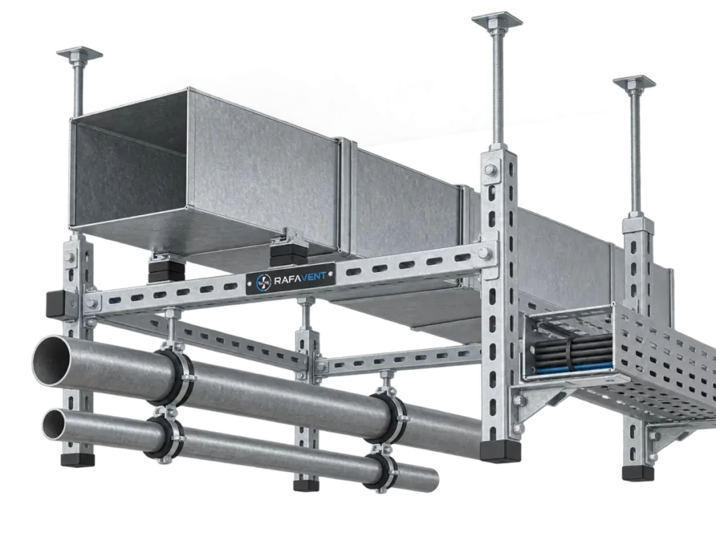
Trapeze & ceiling supports
Single- or multi-profile suspended frames for ducts, pipes and cable routes.
Wall, floor & equipment frames
Brackets, cantilevers, bases and modular frames for plantrooms and service zones.
Coordinated multi-service supports
Shared assemblies engineered around combined loads, clearances, movement and installation sequence.
Coordinated product range
| Product group | Arrangement | Control note |
|---|---|---|
| Support Profiles / strut channels | Single or back-to-back sections | Size, thickness, grade and finish per controlled datasheet |
| Brackets and cantilevers | Wall, ceiling and frame connections | Capacity depends on geometry, fixing and load direction |
| Base plates and connectors | Frame nodes and structural interfaces | Check plate, bolts, welds and eccentricity |
| Channel and spring nuts | Profile connections | Thread, engagement and compatibility must match |
| Threaded rods and accessories | Suspended supports | Diameter, grade, length, buckling and rod bracing |
| Pipe / duct / beam clamps | Service and structure connection | Diameter, lining, temperature and base interface |
| Anchors and fasteners | Concrete, steel or approved substrate | Exact anchor approval and installation parameters required |
Mandatory engineering inputs
| Input | Required definition |
|---|---|
| Service loads | Empty, operating, insulated, fluid and point loads |
| Support geometry | Span, cantilever, drop, eccentricity and member orientation |
| Load cases | Dead, imposed, thermal, vibration, wind and maintenance loads |
| Substrate | Concrete strength, steel grade, edge distance, embedment and access |
| Environment | Indoor/outdoor, moisture, chemical exposure and corrosion category |
| Movement | Thermal expansion, flexible points, guides and anchors |
| Special requirements | Seismic, fire, acoustic or fatigue requirement only when specified |
Required verification checks
| Check | Engineering requirement |
|---|---|
| Members | Bending, shear, interaction, local effects and utilization |
| Deflection | Project serviceability limit at operating load |
| Connections | Bolts, channel nuts, plates, welds and slip resistance |
| Threaded rods | Tension, combined action, unbraced length and buckling where relevant |
| Anchors | Tension/shear interaction, concrete condition, edge/group effects |
| Load path | Continuous transfer from service to primary structure |
| Compatibility | Coating, galvanic contact, temperature and manufacturer interfaces |
Controlled project deliverables
| Deliverable | Controlled content |
|---|---|
| Selection basis | Codes, load assumptions, safety factors and exclusions |
| Support schedule | Tag, arrangement, span, components and quantities |
| Drawings | Typical details and project-specific coordinated locations |
| BOM / BOQ | Profiles, plates, rods, clamps, nuts, anchors and fasteners |
| Product evidence | Datasheets, material/finish declarations and applicable approvals |
| Calculation note | Issued only when included and reviewed within project scope |
| Installation / inspection | Torque, embedment, spacing, field changes and acceptance records |
RAFAVENT
Engineering boundary: No universal allowable-load table applies to every Support Profile arrangement. Capacity depends on section, thickness, material grade, span, orientation, connection, anchor, substrate and load case. Structural, seismic, fire-resistance, corrosion-life or equivalence claims apply only when supported by the exact approved product and project documentation.
Need engineering support?
Send the service loads, support geometry, substrate, operating environment, installation constraints and available project documents. RAFAVENT will review the information before proposing a suitable support arrangement.
Request Engineering ReviewLoad Capacity & Deflection
Engineering status: Not applicable to structural support products. Engineering output is expressed through load capacity, utilization, deflection and connection checks rather than an aerodynamic curve.
Dimensions
Profile size, span, cantilever, drop, rod length, plate geometry, fixing centres and coordinated service clearances are defined on the support schedule and project drawings.
Construction & Materials
Profile and plate grade, thickness, rods, channel nuts, anchors, bolts, welds and protective finish are specified for the loads, substrate and corrosion environment.
Load Path & Structural Interfaces
No drive arrangement applies. The equivalent controlled interface is the load path from supported services through members, connections and anchors to the building structure.
Technical Documentation
Selection basis, calculation sheet, support schedule, coordinated drawings, BOM/BOQ, material and finish declarations, installation details and approved product evidence are controlled deliverables.