

RAFAVENT SYSTEM COMPLETION
Accessories & Controls
Mechanical accessories, vibration and acoustic components, drives, sensors and control interfaces coordinated with the selected fan and project control philosophy.
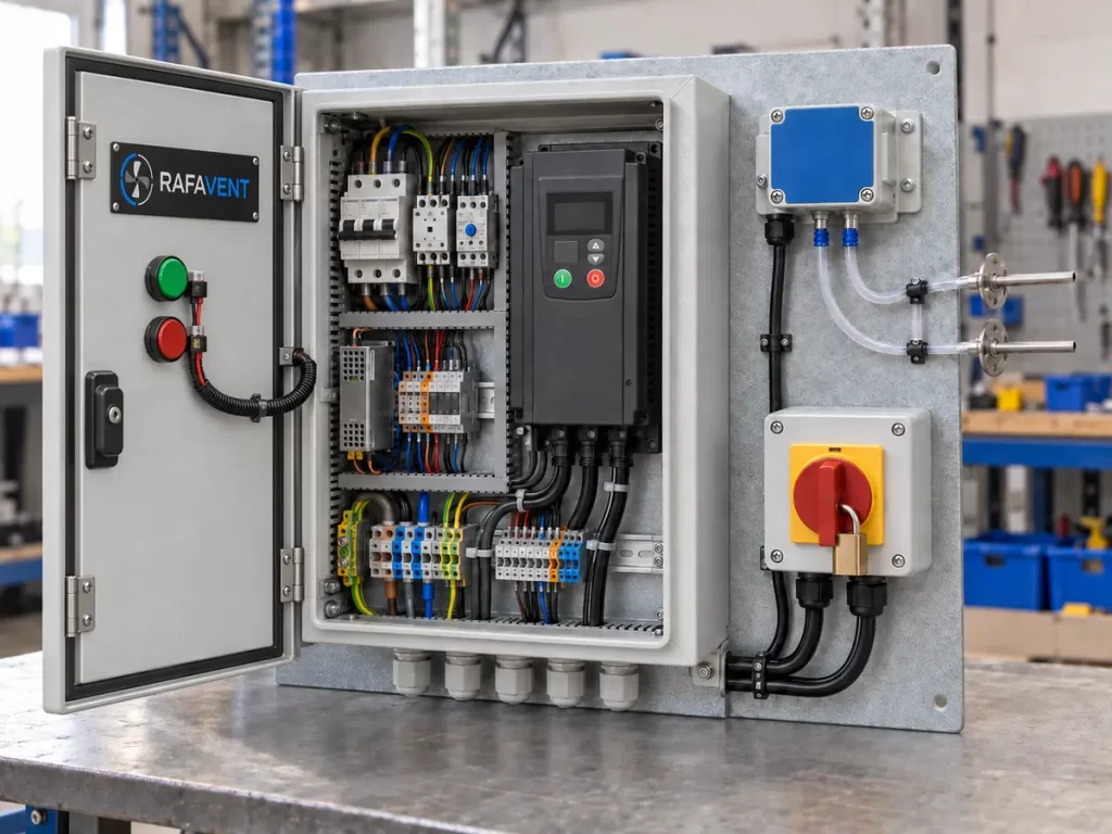
Compatibility boundary: accessory ratings are not universal. Electrical, mechanical, ingress-protection, temperature, fire and control characteristics apply only to the exact selected component and documented interface.
Accessory groups
Mechanical interfaces
Flexible connectors, transitions, flanges, guards, screens and service-access components.
Vibration and acoustics
Rubber or spring isolators, inertia/base coordination, silencers and connection details.
Electrical and control
VFDs, switches, sensors, alarm contacts, BMS interfaces and project control logic.
Accessory compatibility matrix
| Code | Component | Available basis | Mandatory matching data |
|---|---|---|---|
| RF-AC-VFD | Variable-frequency drive | 0.37–132 kW project-matched | Motor current, voltage, overload, EMC, cable length, enclosure and control sequence |
| RF-AC-ISO | Vibration isolators | Rubber or spring | Operating weight, centre of gravity, deflection, disturbing frequency and support structure |
| RF-AC-FLEX | Flexible connections | Round or rectangular | Connection size, temperature, pressure, movement, fabric and grounding continuity |
| RF-AC-GRD | Guards and screens | Inlet, outlet, belt or coupling | Opening, access, material, corrosion protection and safe clearance |
| RF-AC-SIL | Silencers and transitions | Circular or rectangular | Airflow, velocity, insertion loss target, pressure loss, length and fire/material requirement |
| RF-AC-SEN | Sensors and control interfaces | Pressure, temperature, CO/CO₂ or status | Range, accuracy, output signal, power, BMS protocol, alarm and fail-safe logic |
Required coordination data
| Required field | Project definition |
|---|---|
| Selected fan | Exact model, duty point, speed, absorbed power, weight and arrangement |
| Electrical supply | Voltage, phase, frequency, fault level, earthing and local regulations |
| Control sequence | Start/stop, setpoint, modulation, interlocks, alarm, override and fail-safe |
| Environment | Indoor/outdoor, temperature, humidity, dust, corrosion and hazardous classification |
| Mechanical connection | Dimensions, flange, movement, access, support and allowable transmitted load |
| Acoustic requirement | Measurement location, target spectrum/level and allowable pressure loss |
| Cable and EMC | Motor cable length, shielding, filters/reactors and BMS segregation |
| Evidence and scope | Supplier datasheet, wiring, certificates, responsibility boundary and commissioning |
Interface and release responsibilities
| Interface | Must be verified | Released document |
|---|---|---|
| Fan ↔ VFD | Motor current, frequency range, insulation, minimum speed and resonance exclusion | VFD schedule, parameters and wiring |
| Fan ↔ isolator/base | Operating weight, centre of gravity, disturbing frequency and structure | Isolator selection and mounting layout |
| Fan ↔ flexible connector | Pressure, temperature, movement, material and grounding | Connection detail and material specification |
| Fan ↔ silencer/transition | Velocity profile, system effect, pressure loss and access | GA/interface drawing and acoustic basis |
| Controls ↔ BMS | Signals, protocol, addressing, alarms and override logic | I/O list, sequence and points schedule |
| Safety interface | Guards, isolator switch, emergency stop and access zones | Safety/access note and responsibility matrix |
Coordination workflow
- Identify the exact fan, duty point and installation arrangement.
- Define electrical, mechanical, acoustic and control interfaces.
- Select components from their documented ratings and compatibility limits.
- Issue coordinated schedules, wiring and interface drawings.
- Commission and record settings, alarms, rotation and protective functions.
Performance Curve
Engineering status: Not applicable as one universal curve. Pressure loss, insertion loss, isolator response or VFD operating data are issued for the selected accessory and matched fan.
Dimensions
Connection size, flange, length, movement allowance, service access and mounting interface are matched to the selected fan and released on the interface or GA drawing.
Construction & Materials
Material, fabric, elastomer, spring, steel grade, enclosure, coating, corrosion protection and grounding continuity are selected from the service conditions.
Drive Arrangement
Drive-related accessories include matched VFDs, belt and coupling guards, isolators and control interfaces. Ratings and compatibility must follow the selected motor and fan arrangement.
Technical Documentation
Accessory datasheet, compatibility schedule, interface drawing, material specification, wiring or I/O data, installation instructions and applicable approved evidence are supplied by item.
Request an engineering selection
Send the duty point, installation arrangement, operating conditions and available drawings for a project-specific selection.
Send project requirements