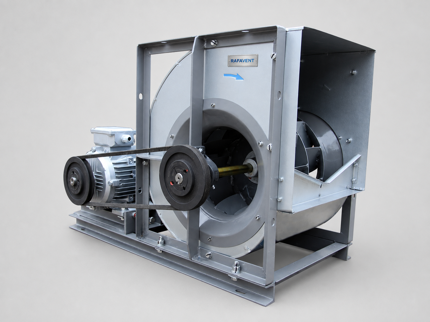
Double-inlet centrifugal arrangement for duties requiring balanced two-sided air entry.
Representative belt-driven configuration. Belt and pulley guards must be fitted before operation.
RAFAVENT RF-CF-BCD SERIES
Backward-Curved Double-Inlet Centrifugal Fans — Technical Selection Data
Double-width, double-inlet backward-curved centrifugal fans for AHUs, base-mounted ventilation assemblies and large-volume MEP air systems.
RAFAVENT Engineering Calculation — Preliminary Selection — Non-Certified. Values are calculated at 20 °C and standard air density 1.20 kg/m³ using fan-law scaling and engineering assumptions. They are not laboratory-certified ratings. Airflow, pressure, power and sound values are not simultaneous guarantees. Final selection requires a confirmed duty point, inlet arrangement, drive side and approved production drawing.
Construction and application
Double-width scroll casing with two unobstructed inlets and a backward-curved steel impeller.
Shaft carried by bearings on both casing sides; bearing selection, service access and lubrication arrangement are confirmed by order.
Belt-drive preliminary basis with motor on base frame. State drive side when viewed from the inlet and confirm rotation/discharge orientation.
Three-phase IEC motor basis, IP55 and Class F specification subject to the approved motor datasheet.
Clean or lightly dust-laden non-corrosive air, preliminary ambient duty −20 to +50 °C. No ATEX, smoke or high-temperature certification is claimed.
Standard model series Ø200–Ø800. Larger construction up to Ø1600 is custom capability only after engineering review and is not a standard catalogued model.
Model selection table
Model
Wheel Ø mm
rpm
Recommended Q m³/h
Recommended Ps Pa
Calculated max Q
Calculated peak Ps
Est. shaft kW
Preliminary motor selection kW
Supply
Est. LpA @3m dB(A)
Drive basis
RF-CF-BCD-200
200
1450
194–354
40–85
432
100
0.01
0.12
230/400 V 3Ph
52 ±6
Belt drive; drive side by order
RF-CF-BCD-250
250
1450
379–691
62–132
843
156
0.03
0.12
230/400 V 3Ph
52 ±6
Belt drive; drive side by order
RF-CF-BCD-315
315
1450
759–1,382
99–210
1,686
247
0.08
0.12
230/400 V 3Ph
53 ±6
Belt drive; drive side by order
RF-CF-BCD-355
355
1450
1,086–1,979
126–267
2,413
314
0.15
0.18
230/400 V 3Ph
55 ±6
Belt drive; drive side by order
RF-CF-BCD-400
400
1450
1,553–2,831
159–339
3,452
398
0.28
0.37
230/400 V 3Ph
57 ±6
Belt drive; drive side by order
RF-CF-BCD-450
450
1450
2,212–4,031
202–429
4,915
504
0.5
0.75
230/400 V 3Ph
59 ±6
Belt drive; drive side by order
RF-CF-BCD-500
500
1450
3,034–5,529
249–529
6,742
623
0.85
1.1
230/400 V 3Ph
62 ±6
Belt drive; drive side by order
RF-CF-BCD-560
560
1450
4,263–7,768
312–664
9,473
781
1.5
2.2
230/400 V 3Ph
64 ±6
Belt drive; drive side by order
RF-CF-BCD-630
630
1450
6,069–11,060
395–840
13,488
988
2.7
4
400/690 V 3Ph
66 ±6
Belt drive; drive side by order
RF-CF-BCD-710
710
960
5,752–10,481
220–468
12,782
550
1.42
2.2
230/400 V 3Ph
62 ±6
Belt drive; drive side by order
RF-CF-BCD-800
800
960
8,228–14,993
279–594
18,285
699
2.58
3
230/400 V 3Ph
64 ±6
Belt drive; drive side by order
Recommended flow and pressure ranges define an intended preliminary selection envelope; they are not opposite corners of a guaranteed duty point. Estimated free-field A-weighted sound pressure at 3 m has ±6 dB(A) uncertainty before casing, duct, reflection, inlet, outlet, belt guard, silencer and system effects.
Calculated model curves
Open a model to view its six-point preliminary Q–Ps curve.
RF-CF-BCD-200 — calculated Q–Ps curve
Point
Q (m³/h)
Ps (Pa)
1
0
72
2
86
92
3
173
100
4
259
86
5
345
52
6
432
0
RF-CF-BCD-250 — calculated Q–Ps curve
Point
Q (m³/h)
Ps (Pa)
1
0
112
2
169
143
3
337
156
4
506
134
5
674
81
6
843
0
RF-CF-BCD-315 — calculated Q–Ps curve
Point
Q (m³/h)
Ps (Pa)
1
0
178
2
337
227
3
674
247
4
1,012
212
5
1,349
128
6
1,686
0
RF-CF-BCD-355 — calculated Q–Ps curve
Point
Q (m³/h)
Ps (Pa)
1
0
226
2
483
289
3
965
314
4
1,448
270
5
1,931
163
6
2,413
0
RF-CF-BCD-400 — calculated Q–Ps curve
Point
Q (m³/h)
Ps (Pa)
1
0
287
2
690
367
3
1,381
398
4
2,071
343
5
2,762
207
6
3,452
0
RF-CF-BCD-450 — calculated Q–Ps curve
Point
Q (m³/h)
Ps (Pa)
1
0
363
2
983
464
3
1,966
504
4
2,949
434
5
3,932
262
6
4,915
0
RF-CF-BCD-500 — calculated Q–Ps curve
Point
Q (m³/h)
Ps (Pa)
1
0
448
2
1,348
573
3
2,697
623
4
4,046
535
5
5,394
324
6
6,742
0
RF-CF-BCD-560 — calculated Q–Ps curve
Point
Q (m³/h)
Ps (Pa)
1
0
562
2
1,895
718
3
3,789
781
4
5,684
672
5
7,578
406
6
9,473
0
RF-CF-BCD-630 — calculated Q–Ps curve
Point
Q (m³/h)
Ps (Pa)
1
0
712
2
2,698
909
3
5,395
988
4
8,093
850
5
10,790
514
6
13,488
0
RF-CF-BCD-710 — calculated Q–Ps curve
Point
Q (m³/h)
Ps (Pa)
1
0
396
2
2,556
506
3
5,113
550
4
7,669
473
5
10,225
286
6
12,782
0
RF-CF-BCD-800 — calculated Q–Ps curve
Point
Q (m³/h)
Ps (Pa)
1
0
503
2
3,657
643
3
7,314
699
4
10,971
601
5
14,628
363
6
18,285
0
Selection requirements
Confirm airflow, static pressure, air density, temperature, conveyed-air composition, both inlet conditions, base/AHU arrangement, drive side, rotation and discharge position, pulley ratio, motor voltage, control method, corrosion class, permissible sound level, access space and accessories before order.
Technical documents, dimensions and service
Technical documents and dimensions
Final dimensions, connection details, materials, motor data and project drawings are issued for the selected configuration after engineering review.
Installation and maintenance
Provide level support, flexible connections, guarded drive components, alignment checks and safe maintenance access. Follow the approved project-specific O&M document.
Selection tables and calculated curves on this page are preliminary engineering guidance, not certified RAFAVENT test ratings. Confirm the operating point and controlled documents before order.
Information required before selection
Required airflow and static pressure
Operating temperature and conveyed-air composition
Installation orientation, space and connection details
Electrical supply, control method and duty pattern
Sound, material and environmental constraints
Request an engineering selection
Send the duty point, installation arrangement, operating conditions and available drawings for a project-specific selection.
RAFAVENT uses essential storage to keep this website secure and working. With your permission, optional services may be used for analytics or interactive features. You can accept all, reject optional services, or manage your choices. See our Privacy Policy and Cookie Policy for details.
Functional
Always active
The technical storage or access is strictly necessary for the legitimate purpose of enabling the use of a specific service explicitly requested by the subscriber or user, or for the sole purpose of carrying out the transmission of a communication over an electronic communications network.
Preferences
The technical storage or access is necessary for the legitimate purpose of storing preferences that are not requested by the subscriber or user.
Statistics
The technical storage or access that is used exclusively for statistical purposes.The technical storage or access that is used exclusively for anonymous statistical purposes. Without a subpoena, voluntary compliance on the part of your Internet Service Provider, or additional records from a third party, information stored or retrieved for this purpose alone cannot usually be used to identify you.
Marketing
The technical storage or access is required to create user profiles to send advertising, or to track the user on a website or across several websites for similar marketing purposes.