

RAFAVENT AXIAL FAN SUBFAMILY
High-Pressure Guide-Vane Axial Fans
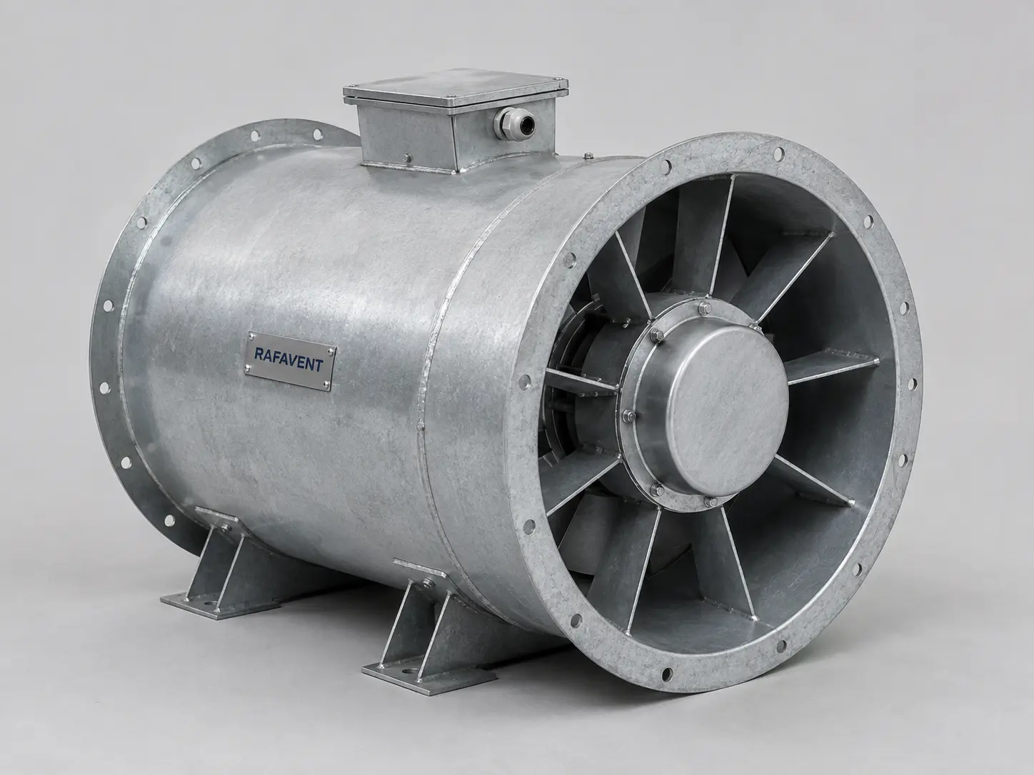
Single-stage axial fans with downstream stationary vanes that recover part of the discharge swirl as useful static pressure and produce a straighter outlet flow for ducted industrial systems.
How the guide-vane configuration is selected
Pressure recovery
Downstream vanes reduce rotational discharge energy and convert a portion of it into static pressure. The achievable gain depends on rotor loading and vane matching.
Controlled discharge
Straighter outlet flow improves downstream pressure measurement and reduces the uncertainty associated with fittings exposed to strong swirl.
Industrial construction
Flanged steel casing, adjustable-pitch axial impeller, welded motor support and fixed guide-vane module; coating and material are selected for the conveyed air.
Preliminary technical selection table
| Model | Impeller Ø (mm) | Airflow range (m³/h) | Static pressure range (Pa) | Speed range (rpm) | Preliminary motor range (kW) | Supply | Acoustic data status |
|---|---|---|---|---|---|---|---|
| AX-GV-400 | 400 | 3,500–7,500 | 300–700 | 1,450–2,900 | 1.5–3 | 400 V / 50 Hz / 3~ | Test data required |
| AX-GV-500 | 500 | 6,500–13,000 | 400–900 | 960–1,450 | 3–5.5 | 400 V / 50 Hz / 3~ | Test data required |
| AX-GV-560 | 560 | 8,500–17,500 | 450–1,050 | 960–1,450 | 4–7.5 | 400 V / 50 Hz / 3~ | Test data required |
| AX-GV-630 | 630 | 12,000–25,000 | 500–1,200 | 720–1,450 | 5.5–11 | 400 V / 50 Hz / 3~ | Test data required |
| AX-GV-710 | 710 | 17,000–34,000 | 550–1,350 | 720–1,450 | 7.5–15 | 400 V / 50 Hz / 3~ | Test data required |
| AX-GV-800 | 800 | 24,000–48,000 | 600–1,500 | 720–980 | 11–22 | 400 V / 50 Hz / 3~ | Test data required |
| AX-GV-900 | 900 | 33,000–65,000 | 650–1,650 | 560–980 | 15–30 | 400 V / 50 Hz / 3~ | Test data required |
| AX-GV-1000 | 1000 | 44,000–85,000 | 700–1,800 | 480–980 | 18.5–37 | 400 V / 50 Hz / 3~ | Test data required |
Acoustic performance for this configuration is not verified for acoustic selection. Specify LwA or LpA, frequency bands, duty point, sound path and test method; LpA also requires measurement distance and environment. A fixed ±6 dB uncertainty without supporting analysis and test documentation is not a verified uncertainty.
Application: process ventilation, filtration and drying systems, industrial supply/extract ducts, equipment cooling and installations requiring more static pressure than a standard tube-axial arrangement.
Installation: horizontal or vertical duct mounting subject to motor, bearing, access and structural review. Provide uniform inlet flow, adequate straight duct where practicable and flexible connections or vibration isolation where required.
Calculated pressure–airflow envelopes
The curves below are diameter-specific preliminary envelopes. The low-flow side of a vane-axial curve can include an unstable or stall region; continuous selection must remain inside the reviewed operating band. The 90% airflow row is an interpolated preliminary point between the 75% and 100% envelope references.
AX-GV-400 calculated envelope
| Airflow Q (m³/h) | Static pressure Ps (Pa) | Operating region |
|---|---|---|
| 0 | 850 | Shut-off reference |
| 1,900 | 820 | Low-flow / stall-margin check |
| 3,800 | 760 | Preferred selection band |
| 5,700 | 600 | High-flow selection band |
| 6,750 | 440 | Approaching free-delivery side (interpolated) |
| 7,500 | 330 | Free-delivery-side reference |
AX-GV-500 calculated envelope
| Airflow Q (m³/h) | Static pressure Ps (Pa) | Operating region |
|---|---|---|
| 0 | 1100 | Shut-off reference |
| 3,300 | 1060 | Low-flow / stall-margin check |
| 6,500 | 980 | Preferred selection band |
| 9,800 | 770 | High-flow selection band |
| 11,700 | 560 | Approaching free-delivery side (interpolated) |
| 13,000 | 420 | Free-delivery-side reference |
AX-GV-560 calculated envelope
| Airflow Q (m³/h) | Static pressure Ps (Pa) | Operating region |
|---|---|---|
| 0 | 1280 | Shut-off reference |
| 4,400 | 1230 | Low-flow / stall-margin check |
| 8,800 | 1135 | Preferred selection band |
| 13,200 | 890 | High-flow selection band |
| 15,750 | 645 | Approaching free-delivery side (interpolated) |
| 17,500 | 485 | Free-delivery-side reference |
AX-GV-630 calculated envelope
| Airflow Q (m³/h) | Static pressure Ps (Pa) | Operating region |
|---|---|---|
| 0 | 1470 | Shut-off reference |
| 6,300 | 1410 | Low-flow / stall-margin check |
| 12,500 | 1300 | Preferred selection band |
| 18,800 | 1020 | High-flow selection band |
| 22,500 | 740 | Approaching free-delivery side (interpolated) |
| 25,000 | 555 | Free-delivery-side reference |
AX-GV-710 calculated envelope
| Airflow Q (m³/h) | Static pressure Ps (Pa) | Operating region |
|---|---|---|
| 0 | 1650 | Shut-off reference |
| 8,500 | 1585 | Low-flow / stall-margin check |
| 17,000 | 1460 | Preferred selection band |
| 25,500 | 1145 | High-flow selection band |
| 30,600 | 835 | Approaching free-delivery side (interpolated) |
| 34,000 | 625 | Free-delivery-side reference |
AX-GV-800 calculated envelope
| Airflow Q (m³/h) | Static pressure Ps (Pa) | Operating region |
|---|---|---|
| 0 | 1830 | Shut-off reference |
| 12,000 | 1760 | Low-flow / stall-margin check |
| 24,000 | 1620 | Preferred selection band |
| 36,000 | 1270 | High-flow selection band |
| 43,200 | 920 | Approaching free-delivery side (interpolated) |
| 48,000 | 690 | Free-delivery-side reference |
AX-GV-900 calculated envelope
| Airflow Q (m³/h) | Static pressure Ps (Pa) | Operating region |
|---|---|---|
| 0 | 2010 | Shut-off reference |
| 16,300 | 1930 | Low-flow / stall-margin check |
| 32,500 | 1780 | Preferred selection band |
| 48,800 | 1395 | High-flow selection band |
| 58,500 | 1015 | Approaching free-delivery side (interpolated) |
| 65,000 | 760 | Free-delivery-side reference |
AX-GV-1000 calculated envelope
| Airflow Q (m³/h) | Static pressure Ps (Pa) | Operating region |
|---|---|---|
| 0 | 2200 | Shut-off reference |
| 21,300 | 2110 | Low-flow / stall-margin check |
| 42,500 | 1945 | Preferred selection band |
| 63,800 | 1525 | High-flow selection band |
| 76,500 | 1110 | Approaching free-delivery side (interpolated) |
| 85,000 | 830 | Free-delivery-side reference |
Engineering selection notes
- The guide-vane module does not automatically justify a smaller motor; final absorbed power must be checked at the selected pitch and density.
- Published standard series: Ø400–1000 mm. Larger custom axial constructions up to Ø1700 mm require separate aerodynamic, shaft, support and vibration analysis and are not represented by these standard envelopes.
- Estimated sound pressure levels are free-field values at 3 m and exclude duct radiation, reflections, silencers, structure-borne vibration and background noise.
- No smoke-temperature class, ATEX status, AMCA rating or EN 12101-3 compliance is claimed unless supported by configuration-specific documentation.
- Final submittal must define airflow, static pressure, air density, temperature, motor, speed control, rotation, installation attitude, material and coating.
Technical documents, dimensions and service
Technical documents and dimensions
Final dimensions, connection details, materials, motor data and project drawings are issued for the selected configuration after engineering review.
Installation and maintenance
Provide level support, flexible connections, guarded drive components, alignment checks and safe maintenance access. Follow the approved project-specific O&M document.
Selection tables and calculated curves on this page are preliminary engineering guidance, not certified RAFAVENT test ratings. Confirm the operating point and controlled documents before order.
Information required before selection
- Required airflow and static pressure
- Operating temperature and conveyed-air composition
- Installation orientation, space and connection details
- Electrical supply, control method and duty pattern
- Sound, material and environmental constraints
Request an engineering selection
Send the duty point, installation arrangement, operating conditions and available drawings for a project-specific selection.
Send project requirements