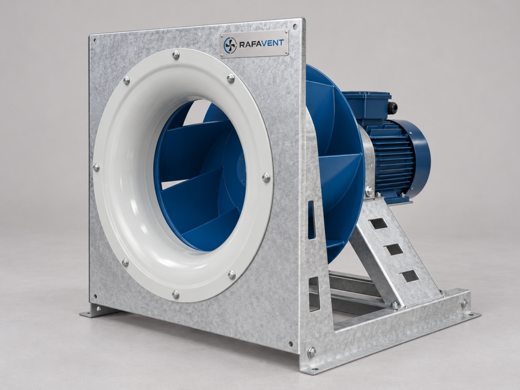
Plug-fan arrangements for integration into air-handling or process enclosures.
Preliminary engineering data
RAFAVENT RF-PF-BC-D SERIES
Industrial Plug / Plenum Fans — Technical Selection Data
Direct-driven, free-running backward-curved impellers for integration into AHU, ventilation and process plenums.
RAFAVENT Engineering Calculation — Preliminary Selection — Non-Certified. Values are calculated at 20 °C and standard air density 1.20 kg/m³ using fan-law scaling and engineering assumptions. They are not laboratory-certified ratings. Final selection requires a confirmed duty point, actual plenum geometry, inlet condition, motor cooling review and approved production drawing.
Construction and integration basis
Backward-curved welded steel wheel, direct-driven without a scroll casing; inlet cone and mounting frame are part of the aerodynamic assembly.
IEC motor with VFD is the standard engineering basis. An EC motor option requires model-specific availability, controller and thermal verification.
Motor rated output is listed, not absorbed electrical input. Motor cooling must be checked for motor-in-air-stream, motor-out-of-air-stream and low-speed VFD operation.
Provide uniform, swirl-free inlet flow. Confirm inlet-cone overlap and running clearance before release.
Minimum preliminary plenum clearance: 0.5 wheel diameter from the nearest discharge obstruction and 1.0 diameter of unobstructed inlet approach; final spacing requires arrangement review.
Wheel balancing and assembled vibration acceptance are required before dispatch.
Clean-air preliminary duty −20 to +50 °C. No ATEX, smoke, fire or high-temperature certification is claimed.
Standard series Ø250–Ø800. Sizes Ø900, Ø1000 and Ø1120 are custom only after structural, shaft, bearing, drive and plenum review.
Model selection table
Model
Wheel Ø mm
Nominal max rpm
Recommended Q m³/h
Recommended Ps Pa
Calculated max Q
Calculated shutoff Ps
Est. shaft kW
Preliminary motor selection kW
Supply
Assembly LpA; test data required
Drive basis
RF-PF-BC-D-250
250
2800
570–1,335
261–696
1,628
870
0.26
0.37
230/400 V 3Ph
Test data required
Direct IEC/VFD or engineered EC option
RF-PF-BC-D-280
280
2500
715–1,674
261–696
2,042
870
0.33
0.55
230/400 V 3Ph
Test data required
Direct IEC/VFD or engineered EC option
RF-PF-BC-D-315
315
2200
895–2,098
256–683
2,558
853
0.41
0.55
230/400 V 3Ph
Test data required
Direct IEC/VFD or engineered EC option
RF-PF-BC-D-355
355
1950
1,136–2,661
255–681
3,245
851
0.51
0.75
230/400 V 3Ph
Test data required
Direct IEC/VFD or engineered EC option
RF-PF-BC-D-400
400
1750
1,458–3,416
261–696
4,166
870
0.68
1.1
230/400 V 3Ph
Test data required
Direct IEC/VFD or engineered EC option
RF-PF-BC-D-450
450
1550
1,839–4,308
259–691
5,254
864
0.85
1.1
230/400 V 3Ph
Test data required
Direct IEC/VFD or engineered EC option
RF-PF-BC-D-500
500
1400
2,278–5,338
261–696
6,510
870
1.06
1.5
230/400 V 3Ph
Test data required
Direct IEC/VFD or engineered EC option
RF-PF-BC-D-560
560
1250
2,858–6,696
261–696
8,166
870
1.32
2.2
230/400 V 3Ph
Test data required
Direct IEC/VFD or engineered EC option
RF-PF-BC-D-630
630
1100
3,581–8,390
256–683
10,232
853
1.63
2.2
230/400 V 3Ph
Test data required
Direct IEC/VFD or engineered EC option
RF-PF-BC-D-710
710
980
4,567–10,699
258–688
13,048
860
2.09
3
230/400 V 3Ph
Test data required
Direct IEC/VFD or engineered EC option
RF-PF-BC-D-800
800
880
5,866–13,744
264–704
16,761
880
2.75
4
400/690 V 3Ph
Test data required
Direct IEC/VFD or engineered EC option
Verified acoustic performance for this configuration has not been published. The previous 56–61 dB values and assumed ±6 dB uncertainty have no documented test basis and are not valid acoustic selection ratings. The lined enclosure is intended to reduce casing-radiated sound; inlet and outlet attenuation depends on ductwork and silencers. Compare enclosed and bare-core configurations at the same airflow, pressure, speed and installation conditions. LwA is sound power and LpA is sound pressure; LpA also requires distance, measurement environment and sound path. Specify frequency bands and test method. Tabulated speed is a calculation reference, not an approved maximum mechanical speed.
Calculated model curves
Open a model to view its six-point preliminary Q–Ps curve.
RF-PF-BC-D-250 — calculated Q–Ps curve
Point
Q (m³/h)
Ps (Pa)
1
0
870
2
326
853
3
651
792
4
976
670
5
1,302
461
6
1,628
0
RF-PF-BC-D-280 — calculated Q–Ps curve
Point
Q (m³/h)
Ps (Pa)
1
0
870
2
408
853
3
817
792
4
1,225
670
5
1,633
461
6
2,042
0
RF-PF-BC-D-315 — calculated Q–Ps curve
Point
Q (m³/h)
Ps (Pa)
1
0
853
2
512
836
3
1,023
776
4
1,535
657
5
2,046
452
6
2,558
0
RF-PF-BC-D-355 — calculated Q–Ps curve
Point
Q (m³/h)
Ps (Pa)
1
0
851
2
649
834
3
1,298
775
4
1,947
656
5
2,596
451
6
3,245
0
RF-PF-BC-D-400 — calculated Q–Ps curve
Point
Q (m³/h)
Ps (Pa)
1
0
870
2
833
853
3
1,667
792
4
2,500
670
5
3,333
461
6
4,166
0
RF-PF-BC-D-450 — calculated Q–Ps curve
Point
Q (m³/h)
Ps (Pa)
1
0
864
2
1,051
847
3
2,102
787
4
3,153
666
5
4,203
458
6
5,254
0
RF-PF-BC-D-500 — calculated Q–Ps curve
Point
Q (m³/h)
Ps (Pa)
1
0
870
2
1,302
853
3
2,604
792
4
3,906
670
5
5,208
461
6
6,510
0
RF-PF-BC-D-560 — calculated Q–Ps curve
Point
Q (m³/h)
Ps (Pa)
1
0
870
2
1,633
853
3
3,266
792
4
4,900
670
5
6,533
461
6
8,166
0
RF-PF-BC-D-630 — calculated Q–Ps curve
Point
Q (m³/h)
Ps (Pa)
1
0
853
2
2,046
836
3
4,093
776
4
6,139
657
5
8,186
452
6
10,232
0
RF-PF-BC-D-710 — calculated Q–Ps curve
Point
Q (m³/h)
Ps (Pa)
1
0
860
2
2,610
843
3
5,219
783
4
7,829
662
5
10,438
456
6
13,048
0
RF-PF-BC-D-800 — calculated Q–Ps curve
Point
Q (m³/h)
Ps (Pa)
1
0
880
2
3,352
863
3
6,704
801
4
10,056
678
5
13,409
467
6
16,761
0
Selection requirements
Confirm airflow, static pressure, air density, temperature, plenum dimensions, inlet approach, inlet-cone geometry, discharge clearance, motor location and cooling, rated motor output, voltage/phase, VFD or EC control method, operating range, corrosion class, permissible sound level and access space before order.
Technical documents, dimensions and service
Technical documents and dimensions
Final dimensions, connection details, materials, motor data and project drawings are issued for the selected configuration after engineering review.
Installation and maintenance
Provide level support, flexible connections, guarded drive components, alignment checks and safe maintenance access. Follow the approved project-specific O&M document.
Selection tables and calculated curves on this page are preliminary engineering guidance, not certified RAFAVENT test ratings. Confirm the operating point and controlled documents before order.
Information required before selection
Required airflow and static pressure
Operating temperature and conveyed-air composition
Installation orientation, space and connection details
Electrical supply, control method and duty pattern
Sound, material and environmental constraints
Request an engineering selection
Send the duty point, installation arrangement, operating conditions and available drawings for a project-specific selection.
RAFAVENT uses essential storage to keep this website secure and working. With your permission, optional services may be used for analytics or interactive features. You can accept all, reject optional services, or manage your choices. See our Privacy Policy and Cookie Policy for details.
Functional
Always active
The technical storage or access is strictly necessary for the legitimate purpose of enabling the use of a specific service explicitly requested by the subscriber or user, or for the sole purpose of carrying out the transmission of a communication over an electronic communications network.
Preferences
The technical storage or access is necessary for the legitimate purpose of storing preferences that are not requested by the subscriber or user.
Statistics
The technical storage or access that is used exclusively for statistical purposes.The technical storage or access that is used exclusively for anonymous statistical purposes. Without a subpoena, voluntary compliance on the part of your Internet Service Provider, or additional records from a third party, information stored or retrieved for this purpose alone cannot usually be used to identify you.
Marketing
The technical storage or access is required to create user profiles to send advertising, or to track the user on a website or across several websites for similar marketing purposes.