

RAFAVENT INLINE & ACOUSTIC SUBFAMILY
Inline Duct Fan Units
Fan units designed for direct integration into circular or rectangular duct routes.
Preliminary engineering data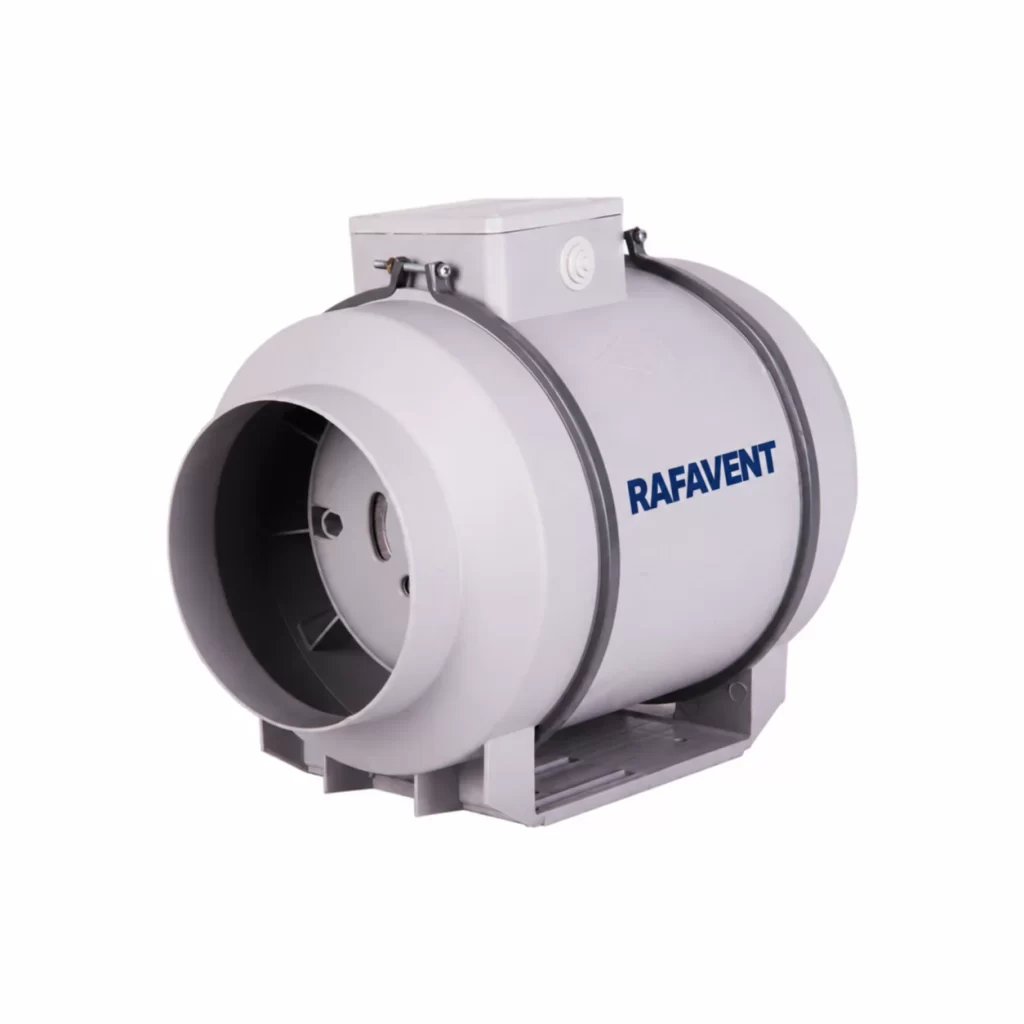
RAFAVENT RF-ID-MF SERIES
Inline Mixed-Flow Duct Fan Units — Technical Selection Data
Compact direct-driven mixed-flow units for circular duct supply and extract duties.
Construction and application
- Galvanized or coated steel cylindrical casing, mixed-flow impeller, downstream guide vanes and direct drive.
- Removable service section and external terminal box; provide safe access without loading the adjacent duct.
- Flexible connectors and independent supports are recommended. Any-orientation installation requires verified support, drainage and terminal-box access.
- Single-phase basis through Ø315; three-phase basis from Ø350. EC execution is an engineered option, not a general claim.
- Preliminary clean-air duty −20 to +50 °C. Not for grease, abrasive dust, smoke control, ATEX or certified high-temperature duty unless separately documented.
- Standard impeller series Ø200, Ø250, Ø280, Ø315, Ø350, Ø400, Ø450 and Ø500.
Model selection table
| Model | Impeller Ø mm | rpm | Recommended Q m³/h | Recommended Ps Pa | Calculated max Q | Calculated shutoff Ps | Est. shaft kW | Preliminary motor selection kW | Supply | Est. LpA @3m dB(A) | Arrangement |
|---|---|---|---|---|---|---|---|---|---|---|---|
| RF-ID-MF-200 | 200 | 2800 | 235–551 | 104–290 | 672 | 371 | 0.05 | 0.12 | 230 V 1Ph | 52 ±6 | Direct mixed-flow |
| RF-ID-MF-250 | 250 | 2800 | 459–1,076 | 162–453 | 1,312 | 580 | 0.15 | 0.18 | 230 V 1Ph | 56 ±6 | Direct mixed-flow |
| RF-ID-MF-280 | 280 | 2800 | 645–1,512 | 204–568 | 1,844 | 728 | 0.26 | 0.37 | 230 V 1Ph | 58 ±6 | Direct mixed-flow |
| RF-ID-MF-315 | 315 | 2800 | 919–2,153 | 258–719 | 2,625 | 921 | 0.47 | 0.55 | 230 V 1Ph | 60 ±6 | Direct mixed-flow |
| RF-ID-MF-350 | 350 | 1450 | 653–1,529 | 85–238 | 1,865 | 305 | 0.11 | 0.18 | 230/400 V 3Ph | 53 ±6 | Direct mixed-flow |
| RF-ID-MF-400 | 400 | 1450 | 974–2,283 | 112–311 | 2,784 | 398 | 0.22 | 0.25 | 230/400 V 3Ph | 55 ±6 | Direct mixed-flow |
| RF-ID-MF-450 | 450 | 1450 | 1,387–3,250 | 141–393 | 3,964 | 504 | 0.39 | 0.55 | 230/400 V 3Ph | 58 ±6 | Direct mixed-flow |
| RF-ID-MF-500 | 500 | 1450 | 1,903–4,459 | 174–486 | 5,438 | 623 | 0.66 | 1.1 | 230/400 V 3Ph | 59 ±6 | Direct mixed-flow |
Selected motor includes a preliminary 15% margin. Estimated sound at 3 m has ±6 dB(A) uncertainty before duct, attenuation, room and installation effects.
Calculated model curves
Open a model to view its six-point preliminary Q–Ps curve.
RF-ID-MF-200 — calculated Q–Ps curve
| Point | Q (m³/h) | Ps (Pa) |
|---|---|---|
| 1 | 0 | 371 |
| 2 | 134 | 364 |
| 3 | 269 | 334 |
| 4 | 403 | 279 |
| 5 | 538 | 186 |
| 6 | 672 | 0 |
RF-ID-MF-250 — calculated Q–Ps curve
| Point | Q (m³/h) | Ps (Pa) |
|---|---|---|
| 1 | 0 | 580 |
| 2 | 262 | 569 |
| 3 | 525 | 522 |
| 4 | 788 | 435 |
| 5 | 1,050 | 290 |
| 6 | 1,312 | 0 |
RF-ID-MF-280 — calculated Q–Ps curve
| Point | Q (m³/h) | Ps (Pa) |
|---|---|---|
| 1 | 0 | 728 |
| 2 | 369 | 713 |
| 3 | 738 | 655 |
| 4 | 1,106 | 546 |
| 5 | 1,475 | 364 |
| 6 | 1,844 | 0 |
RF-ID-MF-315 — calculated Q–Ps curve
| Point | Q (m³/h) | Ps (Pa) |
|---|---|---|
| 1 | 0 | 921 |
| 2 | 525 | 903 |
| 3 | 1,050 | 829 |
| 4 | 1,575 | 691 |
| 5 | 2,100 | 461 |
| 6 | 2,625 | 0 |
RF-ID-MF-350 — calculated Q–Ps curve
| Point | Q (m³/h) | Ps (Pa) |
|---|---|---|
| 1 | 0 | 305 |
| 2 | 373 | 299 |
| 3 | 746 | 275 |
| 4 | 1,119 | 229 |
| 5 | 1,492 | 153 |
| 6 | 1,865 | 0 |
RF-ID-MF-400 — calculated Q–Ps curve
| Point | Q (m³/h) | Ps (Pa) |
|---|---|---|
| 1 | 0 | 398 |
| 2 | 557 | 390 |
| 3 | 1,114 | 359 |
| 4 | 1,670 | 299 |
| 5 | 2,227 | 199 |
| 6 | 2,784 | 0 |
RF-ID-MF-450 — calculated Q–Ps curve
| Point | Q (m³/h) | Ps (Pa) |
|---|---|---|
| 1 | 0 | 504 |
| 2 | 793 | 494 |
| 3 | 1,586 | 454 |
| 4 | 2,378 | 378 |
| 5 | 3,171 | 252 |
| 6 | 3,964 | 0 |
RF-ID-MF-500 — calculated Q–Ps curve
| Point | Q (m³/h) | Ps (Pa) |
|---|---|---|
| 1 | 0 | 623 |
| 2 | 1,088 | 610 |
| 3 | 2,175 | 560 |
| 4 | 3,262 | 467 |
| 5 | 4,350 | 311 |
| 6 | 5,438 | 0 |
Selection requirements
Confirm airflow, static pressure, air density, temperature, duct diameter, upstream and downstream straight length, mounting orientation, service access, voltage/phase, speed-control method, operating range, permissible sound level and conveyed-air composition before order.
Technical documents, dimensions and service
Technical documents and dimensions
Final dimensions, connection details, materials, motor data and project drawings are issued for the selected configuration after engineering review.
Installation and maintenance
Provide level support, flexible connections, guarded drive components, alignment checks and safe maintenance access. Follow the approved project-specific O&M document.
Selection tables and calculated curves on this page are preliminary engineering guidance, not certified RAFAVENT test ratings. Confirm the operating point and controlled documents before order.
Information required before selection
- Required airflow and static pressure
- Operating temperature and conveyed-air composition
- Installation orientation, space and connection details
- Electrical supply, control method and duty pattern
- Sound, material and environmental constraints
Request an engineering selection
Send the duty point, installation arrangement, operating conditions and available drawings for a project-specific selection.
Send project requirements