

RAFAVENT AXIAL FAN SUBFAMILY
Large-Diameter Agricultural Axial Fans
Low-pressure, high-airflow exhaust fans for poultry houses, livestock buildings, greenhouses and agricultural process spaces.
Calculated technical selection data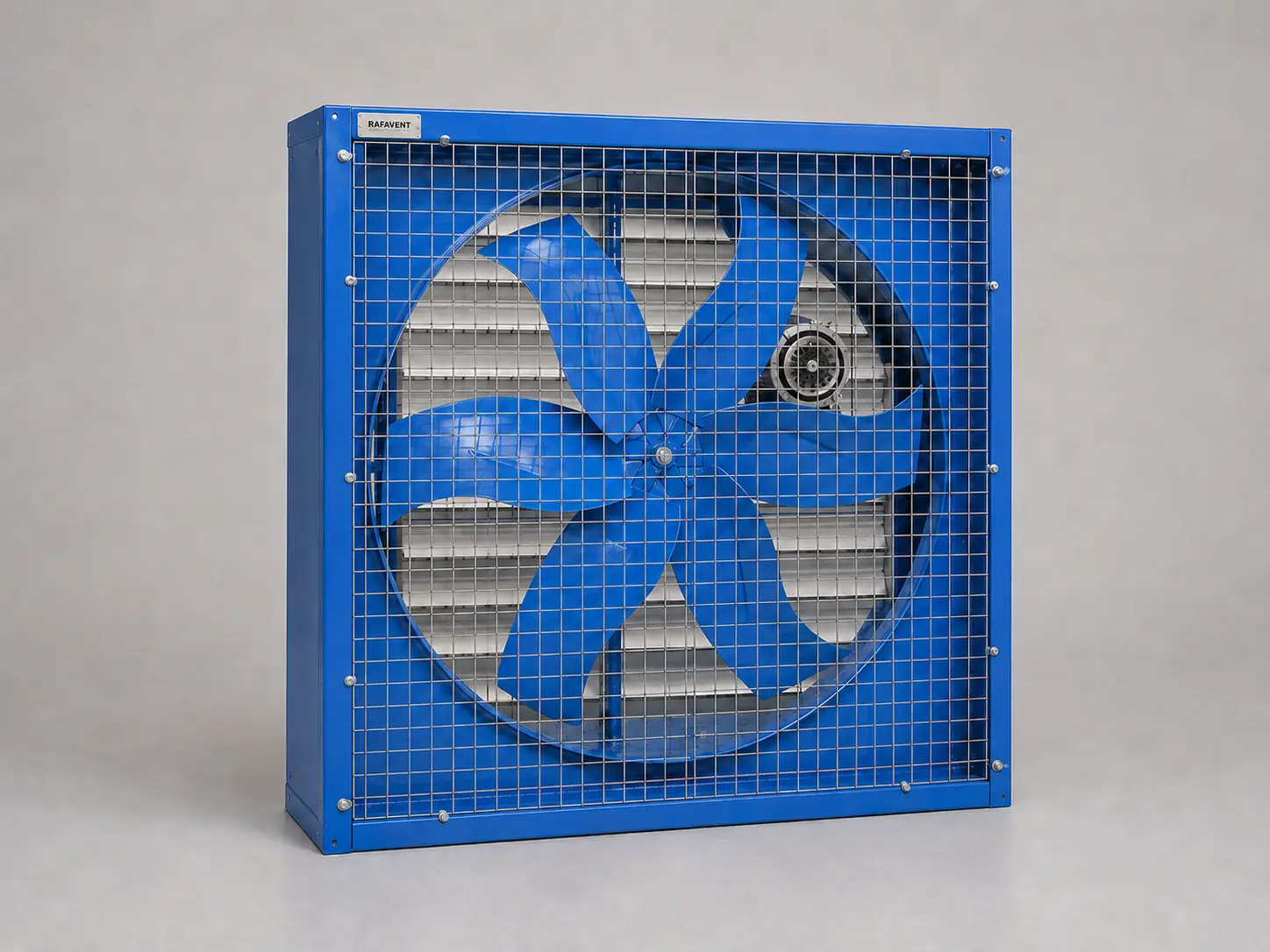
RAFAVENT RF-AGR SERIES
Agricultural & Poultry Exhaust Fans — Technical Selection Data
Wall-mounted axial exhaust fans designed for continuous air exchange at low system resistance; drive arrangement may be direct or belt-driven according to size and project duty.
Construction and application
- Galvanized or coated square housing with protective inlet guard and project-selected shutter or discharge cone.
- Direct-drive or belt-driven aluminium, coated-steel or engineered-composite propeller; final blade material depends on corrosion, cleaning and duty cycle.
- Standard clean-air agricultural basis −20 to +50 °C; humidity, ammonia, dust and wash-down exposure require a project material and motor-IP review.
- Wall or framed-opening exhaust installation with sufficient make-up air; avoid recirculation and inlet blockage.
Model selection table
| Model | Ø mm | rpm | Recommended Q m³/h | Recommended Ps Pa | Max free-air Q | Shut-off Ps | Preliminary motor selection kW | Supply | Est. LpA @3m dB(A) | Approx. housing W × H × D mm | Est. kg |
|---|---|---|---|---|---|---|---|---|---|---|---|
| RF-AGR-560 | 560 | 960 | 7,101–9,833 | 16–50 | 10,925 | 86 | 0.55 | 230 V 1Ph / 400 V 3Ph | 56 ±6 | 683 × 683 × 308 | 46 |
| RF-AGR-630 | 630 | 960 | 10,111–14,000 | 21–63 | 15,555 | 108 | 0.75 | 230 V 1Ph / 400 V 3Ph | 58 ±6 | 769 × 769 × 347 | 50 |
| RF-AGR-710 | 710 | 960 | 14,472–20,039 | 26–80 | 22,265 | 138 | 1.1 | 230 V 1Ph / 400 V 3Ph | 60 ±6 | 866 × 866 × 391 | 54 |
| RF-AGR-800 | 800 | 720 | 15,527–21,499 | 19–57 | 23,888 | 98 | 1.1 | 230 V 1Ph / 400 V 3Ph | 60 ±6 | 976 × 976 × 440 | 59 |
| RF-AGR-900 | 900 | 720 | 22,108–30,611 | 24–72 | 34,012 | 124 | 1.5 | 400 V 3Ph | 63 ±6 | 1098 × 1098 × 495 | 65 |
| RF-AGR-1000 | 1000 | 720 | 30,326–41,990 | 29–89 | 46,656 | 153 | 2.2 | 400 V 3Ph | 65 ±6 | 1220 × 1220 × 550 | 70 |
Recommended airflow and pressure describe a selection envelope, not opposite corners of one guaranteed operating point. Sound is estimated free-field A-weighted sound pressure at 3 m before wall reflection, shutter, cone, guard and building effects; uncertainty ±6 dB(A).
Calculated model curves
Six-point preliminary Q–Ps curves are provided for the standard series. Do not extrapolate beyond free-air flow or shut-off pressure.
RF-AGR-560 — calculated Q–Ps curve
| Point | Q (m³/h) | Ps (Pa) |
|---|---|---|
| 1 | 0 | 86 |
| 2 | 2,731 | 82 |
| 3 | 5,463 | 67 |
| 4 | 7,647 | 47 |
| 5 | 9,286 | 26 |
| 6 | 10,925 | 0 |
RF-AGR-630 — calculated Q–Ps curve
| Point | Q (m³/h) | Ps (Pa) |
|---|---|---|
| 1 | 0 | 108 |
| 2 | 3,889 | 103 |
| 3 | 7,778 | 84 |
| 4 | 10,889 | 59 |
| 5 | 13,222 | 32 |
| 6 | 15,555 | 0 |
RF-AGR-710 — calculated Q–Ps curve
| Point | Q (m³/h) | Ps (Pa) |
|---|---|---|
| 1 | 0 | 138 |
| 2 | 5,566 | 131 |
| 3 | 11,133 | 108 |
| 4 | 15,585 | 76 |
| 5 | 18,925 | 41 |
| 6 | 22,265 | 0 |
RF-AGR-800 — calculated Q–Ps curve
| Point | Q (m³/h) | Ps (Pa) |
|---|---|---|
| 1 | 0 | 98 |
| 2 | 5,972 | 93 |
| 3 | 11,944 | 76 |
| 4 | 16,722 | 54 |
| 5 | 20,305 | 29 |
| 6 | 23,888 | 0 |
RF-AGR-900 — calculated Q–Ps curve
| Point | Q (m³/h) | Ps (Pa) |
|---|---|---|
| 1 | 0 | 124 |
| 2 | 8,503 | 118 |
| 3 | 17,006 | 97 |
| 4 | 23,808 | 68 |
| 5 | 28,910 | 37 |
| 6 | 34,012 | 0 |
RF-AGR-1000 — calculated Q–Ps curve
| Point | Q (m³/h) | Ps (Pa) |
|---|---|---|
| 1 | 0 | 153 |
| 2 | 11,664 | 145 |
| 3 | 23,328 | 119 |
| 4 | 32,659 | 84 |
| 5 | 39,658 | 46 |
| 6 | 46,656 | 0 |
Selection requirements
Confirm required ventilation rate, building static pressure, shutter/cone/guard losses, pad condition, corrosive exposure, voltage, controls, duty cycle, permissible sound and cleaning method before order.
Technical documents, dimensions and service
Technical documents and dimensions
Final dimensions, connection details, materials, motor data and project drawings are issued for the selected configuration after engineering review.
Installation and maintenance
Provide level support, flexible connections, guarded drive components, alignment checks and safe maintenance access. Follow the approved project-specific O&M document.
Selection tables and calculated curves on this page are preliminary engineering guidance, not certified RAFAVENT test ratings. Confirm the operating point and controlled documents before order.
Information required before selection
- Required airflow and static pressure
- Operating temperature and conveyed-air composition
- Installation orientation, space and connection details
- Electrical supply, control method and duty pattern
- Sound, material and environmental constraints
Request an engineering selection
Send the duty point, installation arrangement, operating conditions and available drawings for a project-specific selection.
Send project requirements