

RAFAVENT AXIAL FAN SUBFAMILY
Reversible Axial Fans
Bidirectional axial-flow fans for supply and extract duties where the required airflow direction changes during normal operation. Selection is based on the duty point required in both directions, not on diameter alone.
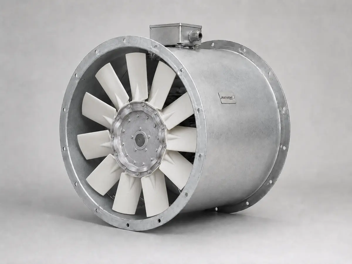
Construction and selection scope
Bidirectional duty
Symmetrical or purpose-designed reversible blades provide comparable forward and reverse operation. Direction-specific tolerance must be confirmed at final selection.
Standard construction
Rolled steel casing with flanged ends, welded motor support, dynamically balanced impeller, external terminal box and protective coating selected for the environment.
Installation
Horizontal or vertical duct installation, wall opening or equipment integration subject to bearing, motor cooling, access and structural review.
Preliminary technical selection table
| Model | Impeller Ø (mm) | Airflow range (m³/h) | Static pressure range (Pa) | Speed range (rpm) | Preliminary motor range (kW) | Supply | Acoustic data status |
|---|---|---|---|---|---|---|---|
| AX-REV-400 | 400 | 3,800–8,000 | 80–250 | 960–1,450 | 0.75–1.5 | 1~/3~ | Test data required |
| AX-REV-500 | 500 | 6,500–14,000 | 100–320 | 720–1,450 | 1.1–3 | 1~/3~ | Test data required |
| AX-REV-560 | 560 | 8,500–18,000 | 120–380 | 720–1,450 | 1.5–4 | 3~ | Test data required |
| AX-REV-630 | 630 | 12,000–26,000 | 150–450 | 720–1,450 | 2.2–5.5 | 3~ | Test data required |
| AX-REV-710 | 710 | 17,000–36,000 | 180–550 | 720–1,450 | 3–7.5 | 3~ | Test data required |
| AX-REV-800 | 800 | 24,000–52,000 | 200–650 | 560–1,450 | 5.5–11 | 3~ | Test data required |
| AX-REV-900 | 900 | 34,000–72,000 | 220–750 | 560–980 | 7.5–15 | 3~ | Test data required |
| AX-REV-1000 | 1000 | 45,000–95,000 | 250–850 | 480–980 | 11–22 | 3~ | Test data required |
Acoustic performance for this configuration is not verified for acoustic selection. Specify LwA or LpA, frequency bands, duty point, sound path and test method; LpA also requires measurement distance and environment. A fixed ±6 dB uncertainty without supporting analysis and test documentation is not a verified uncertainty.
Electrical basis: 230 V single-phase where shown and motor size permits; 400 V, 50 Hz, three-phase for the remaining standard selections. VFD operation is recommended when both operating directions or multiple duty points require commissioning adjustment.
Materials: standard casing in coated carbon steel; galvanised, stainless-steel and project-specific corrosion-protection options are subject to conveyed-air and environmental review. Aluminium or engineered composite blades may be selected by diameter and duty.
Calculated pressure–airflow envelopes
Each table represents a separate preliminary curve envelope for the stated diameter. Select continuous duty away from shut-off, stall and free-delivery limits. Actual curves depend on blade pitch, blade count, hub ratio, tip clearance, motor blockage and test arrangement. The 90% airflow row is an interpolated preliminary point between the 75% and 100% envelope references.
AX-REV-400 calculated envelope
| Airflow Q (m³/h) | Static pressure Ps (Pa) | Relative operating zone |
|---|---|---|
| 0 | 325 | Shut-off reference |
| 2,000 | 310 | Low-flow / avoid continuous duty |
| 4,000 | 285 | Preferred selection band |
| 6,000 | 220 | High-flow selection band |
| 7,200 | 140 | Approaching free-delivery side (interpolated) |
| 8,000 | 90 | Free-delivery reference |
AX-REV-500 calculated envelope
| Airflow Q (m³/h) | Static pressure Ps (Pa) | Relative operating zone |
|---|---|---|
| 0 | 415 | Shut-off reference |
| 3,500 | 395 | Low-flow / avoid continuous duty |
| 7,000 | 360 | Preferred selection band |
| 10,500 | 275 | High-flow selection band |
| 12,600 | 180 | Approaching free-delivery side (interpolated) |
| 14,000 | 115 | Free-delivery reference |
AX-REV-560 calculated envelope
| Airflow Q (m³/h) | Static pressure Ps (Pa) | Relative operating zone |
|---|---|---|
| 0 | 495 | Shut-off reference |
| 4,500 | 470 | Low-flow / avoid continuous duty |
| 9,000 | 425 | Preferred selection band |
| 13,500 | 325 | High-flow selection band |
| 16,200 | 210 | Approaching free-delivery side (interpolated) |
| 18,000 | 135 | Free-delivery reference |
AX-REV-630 calculated envelope
| Airflow Q (m³/h) | Static pressure Ps (Pa) | Relative operating zone |
|---|---|---|
| 0 | 585 | Shut-off reference |
| 6,500 | 555 | Low-flow / avoid continuous duty |
| 13,000 | 505 | Preferred selection band |
| 19,500 | 385 | High-flow selection band |
| 23,400 | 250 | Approaching free-delivery side (interpolated) |
| 26,000 | 160 | Free-delivery reference |
AX-REV-710 calculated envelope
| Airflow Q (m³/h) | Static pressure Ps (Pa) | Relative operating zone |
|---|---|---|
| 0 | 715 | Shut-off reference |
| 9,000 | 680 | Low-flow / avoid continuous duty |
| 18,000 | 615 | Preferred selection band |
| 27,000 | 470 | High-flow selection band |
| 32,400 | 305 | Approaching free-delivery side (interpolated) |
| 36,000 | 195 | Free-delivery reference |
AX-REV-800 calculated envelope
| Airflow Q (m³/h) | Static pressure Ps (Pa) | Relative operating zone |
|---|---|---|
| 0 | 845 | Shut-off reference |
| 13,000 | 800 | Low-flow / avoid continuous duty |
| 26,000 | 725 | Preferred selection band |
| 39,000 | 555 | High-flow selection band |
| 46,800 | 360 | Approaching free-delivery side (interpolated) |
| 52,000 | 230 | Free-delivery reference |
AX-REV-900 calculated envelope
| Airflow Q (m³/h) | Static pressure Ps (Pa) | Relative operating zone |
|---|---|---|
| 0 | 975 | Shut-off reference |
| 18,000 | 925 | Low-flow / avoid continuous duty |
| 36,000 | 835 | Preferred selection band |
| 54,000 | 640 | High-flow selection band |
| 64,800 | 415 | Approaching free-delivery side (interpolated) |
| 72,000 | 265 | Free-delivery reference |
AX-REV-1000 calculated envelope
| Airflow Q (m³/h) | Static pressure Ps (Pa) | Relative operating zone |
|---|---|---|
| 0 | 1105 | Shut-off reference |
| 24,000 | 1050 | Low-flow / avoid continuous duty |
| 48,000 | 945 | Preferred selection band |
| 72,000 | 725 | High-flow selection band |
| 85,500 | 470 | Approaching free-delivery side (interpolated) |
| 95,000 | 300 | Free-delivery reference |
Selection notes
- Specify forward and reverse airflow and pressure separately; do not assume identical system resistance in both directions.
- For emergency smoke duty, no temperature class or EN 12101-3 claim applies unless the complete supplied fan has the relevant certification.
- Sound values are preliminary free-field estimates at 3 m and exclude duct breakout, structure-borne vibration, reflections, silencers and background noise.
- Motor power is a selection range, not a guaranteed installed rating. Final rating includes absorbed-power margin, air density, temperature and control method.
- Standard published series: Ø400–1000 mm. RAFAVENT has axial manufacturing capability up to Ø1700 mm for custom engineered projects; custom sizes require a separate structural and aerodynamic review and are not represented by the standard curves above.
Technical documents, dimensions and service
Technical documents and dimensions
Final dimensions, connection details, materials, motor data and project drawings are issued for the selected configuration after engineering review.
Installation and maintenance
Provide level support, flexible connections, guarded drive components, alignment checks and safe maintenance access. Follow the approved project-specific O&M document.
Selection tables and calculated curves on this page are preliminary engineering guidance, not certified RAFAVENT test ratings. Confirm the operating point and controlled documents before order.
Information required before selection
- Required airflow and static pressure
- Operating temperature and conveyed-air composition
- Installation orientation, space and connection details
- Electrical supply, control method and duty pattern
- Sound, material and environmental constraints
Request an engineering selection
Send the duty point, installation arrangement, operating conditions and available drawings for a project-specific selection.
Send project requirements