

RAFAVENT PROJECT-ENGINEERED FANS
Utility & Custom Fans
Compact utility fans and project-specific axial, centrifugal and packaged fan assemblies developed around the verified duty point, space envelope, environment and documentation scope.
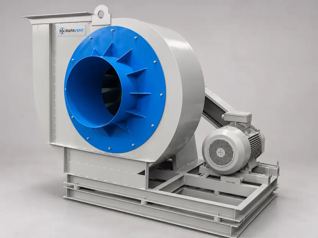
Engineering boundary: dimensional envelopes below describe RAFAVENT manufacturing capability, not a certified performance range. Every custom duty requires a released selection, drawing and evidence status for the exact configuration.
Engineering solution paths
Compact utility fans
Space-efficient direct- or belt-drive arrangements for general service ventilation and equipment areas.
Custom axial and centrifugal fans
Project-designed diameter, casing, wheel, material and drive arrangements for non-standard duties.
OEM and packaged assemblies
Fan, motor, base, guard, silencer, control or plenum coordination within an agreed supply boundary.
Preliminary manufacturing capability
| Series | Configuration | Size / diameter envelope | Drive | Typical scope |
|---|---|---|---|---|
| RF-UF-CMP | Compact utility centrifugal | 200–710 mm | Direct or belt drive | Equipment rooms, service ventilation and constrained spaces |
| RF-UF-CUS | Custom centrifugal | Up to 1,600 mm project envelope | Direct, belt or coupling | Industrial process, material-compatible and high-pressure duties |
| RF-UF-AX | Custom axial | Standard industrial to 1,000 mm; project-built up to 1,700 mm | Direct or project drive | Large-volume process, ventilation and special installation |
| RF-UF-MOD | OEM / packaged module | Project-specific | Integrated module | Machine, skid, plenum or customer-specific assembly |
Required project definition
| Required field | Engineering input |
|---|---|
| Duty point | Airflow, static/total pressure, density, altitude and system resistance |
| Operating range | Minimum, design and maximum duty; continuous/intermittent/emergency schedule |
| Air medium | Temperature, humidity, dust, particles, corrosive or hazardous constituents |
| Space and interfaces | Maximum envelope, inlet/outlet geometry, orientation, base and service access |
| Drive and electrical | Direct/belt/coupling, motor power/speed, supply, VFD and control philosophy |
| Acoustics and vibration | Sound target at stated distance, vibration limit, isolation and flexible connections |
| Materials and finish | Wheel, casing, shaft, coating, corrosion category and wear protection |
| Compliance evidence | Required tests, certificates, inspection, FAT, drawings and document language |
Engineering checks and release documents
| Stage | Mandatory check | Released output |
|---|---|---|
| Aerodynamic selection | Duty point, operating range, density correction and system effect | Selection sheet and performance curve |
| Mechanical design | Wheel stress, shaft, bearings, critical speed, guards and base | GA drawing, rotor/drive definition and BOM |
| Power and drive | Absorbed power across range, service factor, belt/coupling and VFD | Motor/drive schedule and electrical data |
| Noise and vibration | Sound basis, balancing grade, isolation and resonance separation | Acoustic/vibration statement and test requirement |
| Environment | Temperature, corrosion, dust, wear, hazardous or smoke duty | Materials/coating schedule and claim boundary |
| Quality release | Inspection points, balance, run test, FAT and document revision | Approved submittal, ITP/FAT record and data book |
Custom engineering workflow
- Receive the duty point, layout, environment and document requirements.
- Select the closest proven RAFAVENT base fan and identify the required modifications.
- Complete aerodynamic, mechanical, drive, acoustic and environmental checks.
- Issue the technical proposal and controlled drawing for review.
- Manufacture and release only to the approved revision and agreed test plan.
Performance Curve
No single universal performance curve applies to this family. The P–Q curve, absorbed power and operating range are calculated and released for the approved custom configuration.
Project-specific engineering status: Performance curves are a controlled project deliverable after aerodynamic and mechanical selection.
Dimensions
The published manufacturing envelopes are 200–710 mm for compact utility units, up to 1600 mm for custom centrifugal designs and up to 1700 mm for project-built axial designs. Final interfaces and overall dimensions are released on the GA drawing.
Construction & Materials
Wheel, casing, shaft, bearings, guards, base, coating, corrosion category and wear protection are selected from the declared medium and duty, then recorded in the approved material specification.
Drive Arrangement
Direct, belt and coupling arrangements are available as stated in the capability table. The selected arrangement, service factor, guards, alignment and maintenance access are documented per project.
Request an engineering selection
Send the duty point, installation arrangement, operating conditions and available drawings for a project-specific selection.
Send project requirements