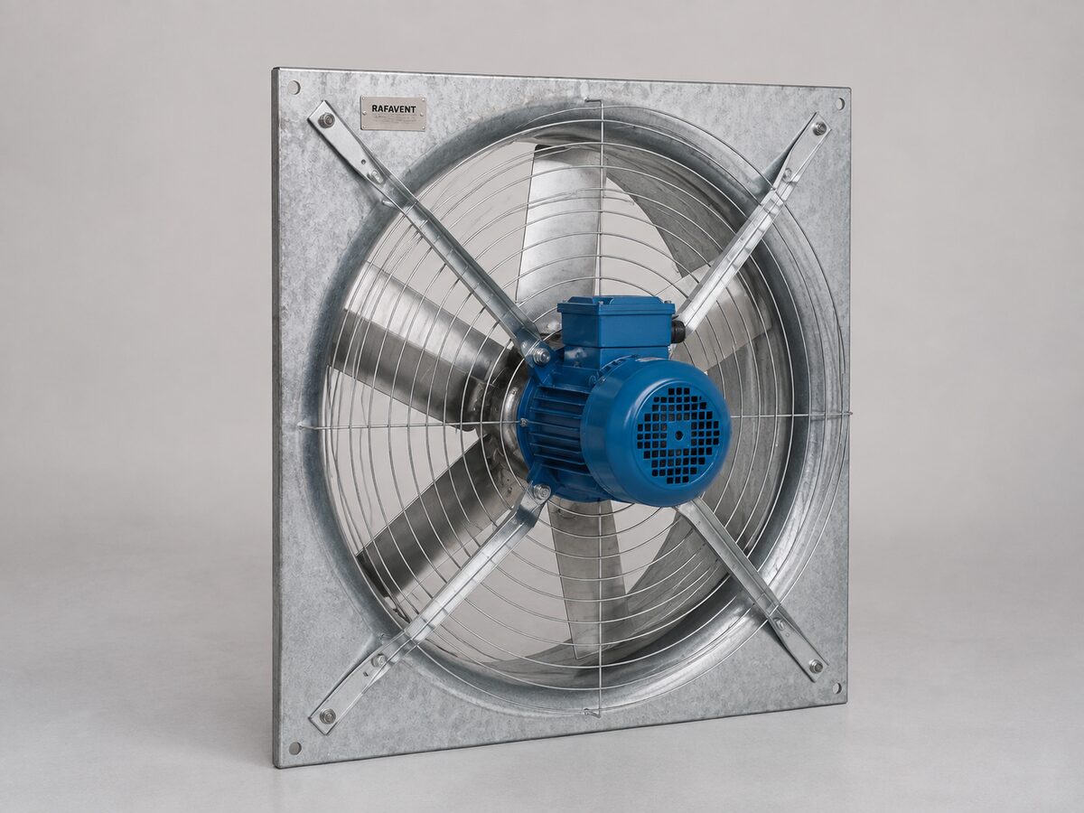
Axial fans configured for direct installation on walls, panels or framed openings where the system requires free-air supply or extract.
Documentation workspaceRAFAVENT wall-mounted axial fan — representative direct-drive configuration.
RAFAVENT RF-AW SERIES
Wall-Mounted Axial Fans — Technical Selection Data
Direct-drive axial fans for free-air or low-resistance wall, panel and framed-opening supply or extract applications.
RAFAVENT Engineering Calculation — Preliminary Selection — Non-Certified. Values are calculated at standard air density 1.20 kg/m³ and are not laboratory-certified ratings. Airflow, shut-off pressure and sound figures are not simultaneous guarantees. Final manufacture and selection require the project duty point and approved production drawing.
Construction and application
Square galvanized or painted steel wall plate with protective guard.
Direct-drive aluminium or engineered composite/steel axial impeller, dynamically balanced during production.
Normal clean-air service; ambient duty basis −20 to +50 °C unless a project-specific motor and material review states otherwise.
Wall or panel mounting; provide unobstructed inlet, make-up air and suitable weather protection where exposed.
Model selection table
Model
Ø mm
rpm
Recommended Q m³/h
Recommended Ps Pa
Max free-air Q
Shut-off Ps
Preliminary motor selection kW
Supply
Est. LpA @3m dB(A)
Approx. envelope mm
Est. kg
RF-AW-200
200
1450
309–495
22–44
618
58
0.12
230 V 1Ph / 400 V 3Ph
42 ±6
340 × 340 × 184
6
RF-AW-250
250
1450
604–966
34–68
1,207
91
0.12
230 V 1Ph / 400 V 3Ph
45 ±6
390 × 390 × 200
6
RF-AW-280
280
1450
848–1,357
43–85
1,696
114
0.12
230 V 1Ph / 400 V 3Ph
48 ±6
420 × 420 × 210
6
RF-AW-315
315
1450
1,208–1,932
55–108
2,415
144
0.12
230 V 1Ph / 400 V 3Ph
51 ±6
455 × 455 × 221
7
RF-AW-355
355
1450
1,729–2,766
70–137
3,457
183
0.18
230 V 1Ph / 400 V 3Ph
54 ±6
495 × 495 × 234
9
RF-AW-400
400
1450
2,473–3,957
88–174
4,946
232
0.25
230 V 1Ph / 400 V 3Ph
57 ±6
540 × 540 × 248
12
RF-AW-450
450
1450
3,521–5,634
112–221
7,042
294
0.55
230 V 1Ph / 400 V 3Ph
60 ±6
590 × 590 × 264
15
RF-AW-500
500
1450
4,830–7,728
138–272
9,660
363
0.75
230 V 1Ph / 400 V 3Ph
63 ±6
640 × 640 × 280
19
RF-AW-560
560
960
4,493–7,188
76–150
8,985
200
0.37
230 V 1Ph / 400 V 3Ph
57 ±6
760 × 760 × 299
23
RF-AW-630
630
960
6,397–10,235
96–190
12,793
253
0.75
230 V 1Ph / 400 V 3Ph
60 ±6
830 × 830 × 322
29
RF-AW-710
710
960
9,156–14,650
122–241
18,312
321
1.5
230 V 1Ph / 400 V 3Ph
63 ±6
910 × 910 × 347
37
RF-AW-800
800
720
9,823–15,718
87–172
19,647
229
1.1
230 V 1Ph / 400 V 3Ph
60 ±6
1000 × 1000 × 376
46
RF-AW-900
900
720
13,987–22,379
110–218
27,974
290
2.2
230 V 1Ph / 400 V 3Ph
63 ±6
1100 × 1100 × 408
57
RF-AW-1000
1000
720
19,187–30,698
136–269
38,373
358
3
400 V 3Ph
66 ±6
1200 × 1200 × 440
69
Recommended Q and Ps columns describe the intended selection envelope; they are not the opposite corners of one guaranteed operating point. Estimated sound is free-field A-weighted sound pressure at 3 m, uncertainty ±6 dB(A), before wall reflection, guards, louvers or system effects.
Calculated model curves
Open a model to view its six-point preliminary Q–Ps curve.
RF-AW-200 — calculated Q–Ps curve
Point
Q (m³/h)
Ps (Pa)
1
0
58
2
124
56
3
247
49
4
371
38
5
495
22
6
618
0
RF-AW-250 — calculated Q–Ps curve
Point
Q (m³/h)
Ps (Pa)
1
0
91
2
241
87
3
483
76
4
724
59
5
966
34
6
1,207
0
RF-AW-280 — calculated Q–Ps curve
Point
Q (m³/h)
Ps (Pa)
1
0
114
2
339
109
3
679
96
4
1,018
74
5
1,357
43
6
1,696
0
RF-AW-315 — calculated Q–Ps curve
Point
Q (m³/h)
Ps (Pa)
1
0
144
2
483
138
3
966
121
4
1,449
94
5
1,932
55
6
2,415
0
RF-AW-355 — calculated Q–Ps curve
Point
Q (m³/h)
Ps (Pa)
1
0
183
2
691
176
3
1,383
154
4
2,074
119
5
2,766
70
6
3,457
0
RF-AW-400 — calculated Q–Ps curve
Point
Q (m³/h)
Ps (Pa)
1
0
232
2
989
223
3
1,978
195
4
2,968
151
5
3,957
88
6
4,946
0
RF-AW-450 — calculated Q–Ps curve
Point
Q (m³/h)
Ps (Pa)
1
0
294
2
1,408
282
3
2,817
247
4
4,225
191
5
5,634
112
6
7,042
0
RF-AW-500 — calculated Q–Ps curve
Point
Q (m³/h)
Ps (Pa)
1
0
363
2
1,932
349
3
3,864
305
4
5,796
236
5
7,728
138
6
9,660
0
RF-AW-560 — calculated Q–Ps curve
Point
Q (m³/h)
Ps (Pa)
1
0
200
2
1,797
192
3
3,594
168
4
5,391
130
5
7,188
76
6
8,985
0
RF-AW-630 — calculated Q–Ps curve
Point
Q (m³/h)
Ps (Pa)
1
0
253
2
2,559
243
3
5,117
212
4
7,676
164
5
10,235
96
6
12,793
0
RF-AW-710 — calculated Q–Ps curve
Point
Q (m³/h)
Ps (Pa)
1
0
321
2
3,662
308
3
7,325
270
4
10,987
209
5
14,650
122
6
18,312
0
RF-AW-800 — calculated Q–Ps curve
Point
Q (m³/h)
Ps (Pa)
1
0
229
2
3,929
220
3
7,859
193
4
11,788
149
5
15,718
87
6
19,647
0
RF-AW-900 — calculated Q–Ps curve
Point
Q (m³/h)
Ps (Pa)
1
0
290
2
5,595
278
3
11,190
244
4
16,784
189
5
22,379
110
6
27,974
0
RF-AW-1000 — calculated Q–Ps curve
Point
Q (m³/h)
Ps (Pa)
1
0
358
2
7,675
344
3
15,349
301
4
23,024
233
5
30,698
136
6
38,373
0
Selection requirements
Confirm airflow, total system resistance, supply/extract direction, voltage and phase, operating temperature, corrosion exposure, control method, permissible sound level and required accessories before order.
Technical documents, dimensions and service
Technical documents and dimensions
Final dimensions, connection details, materials, motor data and project drawings are issued for the selected configuration after engineering review.
Installation and maintenance
Provide level support, flexible connections, guarded drive components, alignment checks and safe maintenance access. Follow the approved project-specific O&M document.
Selection tables and calculated curves on this page are preliminary engineering guidance, not certified RAFAVENT test ratings. Confirm the operating point and controlled documents before order.
Information required before selection
Required airflow and static pressure
Operating temperature and conveyed-air composition
Installation orientation, space and connection details
Electrical supply, control method and duty pattern
Sound, material and environmental constraints
Request an engineering selection
Send the duty point, installation arrangement, operating conditions and available drawings for a project-specific selection.
RAFAVENT uses essential storage to keep this website secure and working. With your permission, optional services may be used for analytics or interactive features. You can accept all, reject optional services, or manage your choices. See our Privacy Policy and Cookie Policy for details.
Functional
Always active
The technical storage or access is strictly necessary for the legitimate purpose of enabling the use of a specific service explicitly requested by the subscriber or user, or for the sole purpose of carrying out the transmission of a communication over an electronic communications network.
Preferences
The technical storage or access is necessary for the legitimate purpose of storing preferences that are not requested by the subscriber or user.
Statistics
The technical storage or access that is used exclusively for statistical purposes.The technical storage or access that is used exclusively for anonymous statistical purposes. Without a subpoena, voluntary compliance on the part of your Internet Service Provider, or additional records from a third party, information stored or retrieved for this purpose alone cannot usually be used to identify you.
Marketing
The technical storage or access is required to create user profiles to send advertising, or to track the user on a website or across several websites for similar marketing purposes.