

RAFAVENT IMPULSE VENTILATION SUBFAMILY
Car-Park Jet Fans
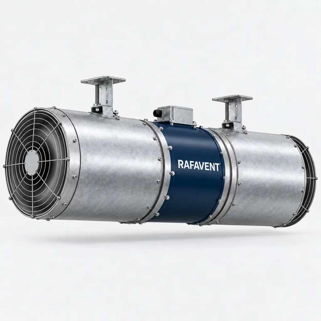
Compact axial impulse fans for directing air through enclosed car parks. Selection is based primarily on required thrust, discharge velocity, layout and CFD coordination—not on static pressure duty.
Selection basis
Thrust-led selection
Nominal thrust is estimated from air density, outlet flow and effective jet velocity. Installed effective thrust is lower when the jet attaches to ceilings, beams or nearby obstacles.
Two-speed operation
Low speed supports routine pollution control and high speed supports purge duty. VFD control may be used where the selected motor and control philosophy permit it.
System coordination
Jet fans move and entrain air toward extract points; main supply and extract fans overcome the system resistance. Final quantity and orientation require layout or CFD review.
Preliminary technical selection table
| Model | Nominal Ø (mm) | Airflow high / low (m³/h) | Outlet velocity high / low (m/s) | Nominal thrust high / low (N) | Preliminary motor selection high / low (kW) | Speed high / low (rpm) | Acoustic data status |
|---|---|---|---|---|---|---|---|
| JF-310-2S | 310 | 4,500 / 2,250 | 16.5 / 8.3 | 25 / 6 | 0.75 / 0.18 | 2,850 / 1,425 | Test data required |
| JF-350-2S | 350 | 6,500 / 3,250 | 18.0 / 9.0 | 40 / 10 | 1.1 / 0.25 | 2,850 / 1,425 | Test data required |
| JF-400-2S | 400 | 9,000 / 4,500 | 20.0 / 10.0 | 60 / 15 | 1.5 / 0.37 | 2,850 / 1,425 | Test data required |
| JF-450-2S | 450 | 12,500 / 6,250 | 22.0 / 11.0 | 90 / 23 | 2.2 / 0.55 | 2,850 / 1,425 | Test data required |
| JF-500-2S | 500 | 16,000 / 8,000 | 23.0 / 11.5 | 125 / 31 | 3.0 / 0.75 | 2,850 / 1,425 | Test data required |
Acoustic performance for this configuration is not verified for acoustic selection. Specify LwA or LpA, frequency bands, duty point, sound path and test method; LpA also requires measurement distance and environment. A fixed ±6 dB uncertainty without supporting analysis and test documentation is not a verified uncertainty.
Electrical basis: 400 V, 50 Hz, three-phase, two-speed or VFD-compatible motor subject to final motor selection. Standard casing is coated or galvanised steel with mounting brackets, protective guards and external terminal box. Silencers are selected separately where the project sound limit requires them.
Calculated thrust build-up by speed
These tables are not pressure–airflow curves. They show six preliminary points at 0%, 25%, 50%, 75%, 90% and 100% speed. Airflow is calculated proportional to speed and nominal thrust proportional to speed squared; displayed thrust is rounded to the nearest newton. Absorbed power changes approximately with the cube of speed.
JF-310-2S calculated thrust build-up
| Command / speed (%) | Airflow (m³/h) | Calculated nominal thrust (N) |
|---|---|---|
| 0 | 0 | 0 |
| 25 | 1,125 | 2 |
| 50 | 2,250 | 6 |
| 75 | 3,375 | 14 |
| 90 | 4,050 | 20 |
| 100 | 4,500 | 25 |
JF-350-2S calculated thrust build-up
| Command / speed (%) | Airflow (m³/h) | Calculated nominal thrust (N) |
|---|---|---|
| 0 | 0 | 0 |
| 25 | 1,625 | 3 |
| 50 | 3,250 | 10 |
| 75 | 4,875 | 23 |
| 90 | 5,850 | 32 |
| 100 | 6,500 | 40 |
JF-400-2S calculated thrust build-up
| Command / speed (%) | Airflow (m³/h) | Calculated nominal thrust (N) |
|---|---|---|
| 0 | 0 | 0 |
| 25 | 2,250 | 4 |
| 50 | 4,500 | 15 |
| 75 | 6,750 | 34 |
| 90 | 8,100 | 49 |
| 100 | 9,000 | 60 |
JF-450-2S calculated thrust build-up
| Command / speed (%) | Airflow (m³/h) | Calculated nominal thrust (N) |
|---|---|---|
| 0 | 0 | 0 |
| 25 | 3,125 | 6 |
| 50 | 6,250 | 23 |
| 75 | 9,375 | 51 |
| 90 | 11,250 | 73 |
| 100 | 12,500 | 90 |
JF-500-2S calculated thrust build-up
| Command / speed (%) | Airflow (m³/h) | Calculated nominal thrust (N) |
|---|---|---|
| 0 | 0 | 0 |
| 25 | 4,000 | 8 |
| 50 | 8,000 | 31 |
| 75 | 12,000 | 70 |
| 90 | 14,400 | 101 |
| 100 | 16,000 | 125 |
Installation and selection notes
- Maintain clear inlet and discharge zones and avoid directing the jet immediately into beams, signs, cable trays, columns or walls.
- Effective installed thrust must be corrected for ceiling proximity, inlet blockage, silencers, deflectors and local cross-flow.
- Sound values are preliminary free-field estimates at 3 m and exclude reflections and structure-borne vibration.
- Routine ventilation data must not be used as proof of emergency smoke performance.
- No F300/F400 temperature class or EN 12101-3 claim applies unless the complete supplied model has valid configuration-specific certification.
- Final system design must define pollution-control rates, extract capacity, fan layout, fire strategy, controls, power supplies and CFD acceptance criteria.
Technical documents, dimensions and service
Technical documents and dimensions
Final dimensions, connection details, materials, motor data and project drawings are issued for the selected configuration after engineering review.
Installation and maintenance
Provide level support, flexible connections, guarded drive components, alignment checks and safe maintenance access. Follow the approved project-specific O&M document.
Selection tables and calculated curves on this page are preliminary engineering guidance, not certified RAFAVENT test ratings. Confirm the operating point and controlled documents before order.
Information required before selection
- Required airflow and static pressure
- Operating temperature and conveyed-air composition
- Installation orientation, space and connection details
- Electrical supply, control method and duty pattern
- Sound, material and environmental constraints
Request an engineering selection
Send the duty point, installation arrangement, operating conditions and available drawings for a project-specific selection.
Send project requirements