

RAFAVENT JET & SMOKE-CONTROL SUBFAMILY
Stairwell Pressurisation Fans
Air-movement equipment for project-specific staircase and protected-route pressurisation systems.
Documentation workspace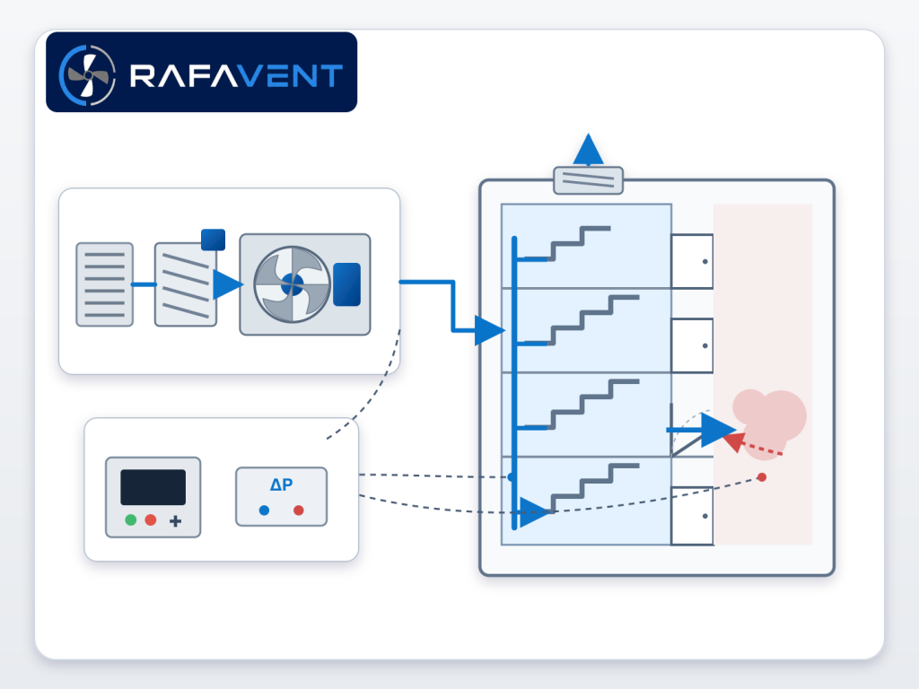
Subfamily scope
Stairwell Pressurisation Fans
This page is reserved for verified technical and commercial documents for this RAFAVENT subfamily.
Technical document centre
Technical document centre
Technical datasheet
Verified construction and selection fields
Performance curves
Airflow and pressure data by confirmed model
Dimensions & CAD
Installation dimensions and available CAD files
Catalogue PDF
Controlled catalogue release for this subfamily
Compliance documents
Only certificates applicable to the supplied configuration
Installation & O&M
Installation, operation and maintenance instructions
Controlled document status
- Technical Datasheet — Available after model selection
- GA Drawing — Project-specific
- Performance Curve — Preliminary data available on page; controlled curve after selection
- CAD — On request after engineering review
- Installation & O&M — Issued with approved supply
- Compliance Documents — Only where applicable to the supplied configuration
Preliminary engineering selection data
Calculated guidance for system screening only. Final pressure targets, open-door airflow, relief area, fan duty and control sequence must be verified against the project fire strategy and applicable local standard.
Design scenarios
| Scenario | Engineering basis | Release condition |
|---|---|---|
| Closed-door pressure control | Differential-pressure sensor + VFD control | Project fire strategy and approved cause-and-effect |
| Open-door make-up airflow | Door-area and required escape-route air velocity | Project fire strategy and approved cause-and-effect |
| Pressure relief / bypass | Relief damper / bypass sized for maximum pressure | Project fire strategy and approved cause-and-effect |
| Commissioning and cause-effect test | Measured pressure, airflow, door force and alarm sequence | Project fire strategy and approved cause-and-effect |
Preliminary RAFAVENT system range
| Model | Max airflow (m³/h) | Reference static pressure (Pa) | Motor estimate (kW) | Control |
|---|---|---|---|---|
| RF-SP-315 | 4,500 | 650 | 1.5 | VFD + pressure sensor |
| RF-SP-400 | 7,500 | 750 | 3 | VFD + pressure sensor |
| RF-SP-450 | 10,000 | 800 | 4 | VFD + pressure sensor |
| RF-SP-500 | 14,000 | 900 | 5.5 | VFD + pressure sensor |
| RF-SP-560 | 19,000 | 1000 | 7.5 | VFD + pressure sensor |
| RF-SP-630 | 26,000 | 1100 | 11 | VFD + pressure sensor |
Illustrative leakage calculation
| Input | Symbol | Illustrative value | Status |
|---|---|---|---|
| Effective leakage area | A | 0.35 m² | Project input |
| Target pressure difference | ΔP | 50 Pa | Illustrative only |
| Discharge coefficient | Cd | 0.65 | Verify |
| Calculated leakage flow | Q | ≈2,050 m³/h | Preliminary |
Control sequence
| State | Fan command | Damper / relief | Verification |
|---|---|---|---|
| Standby | Project-defined | Normal position | BMS healthy |
| Fire alarm | Start / duty command | Open required path | Alarm feedback |
| Door closed | Modulate to pressure setpoint | Relieve excess pressure | Pressure + door force |
| Door open | Increase to airflow demand | Coordinate relief | Air velocity |
| Sensor fault | Approved fallback speed | Safe position | Fault alarm |
System components
| Component | Minimum project definition |
|---|---|
| Supply fan | Duty, redundancy, motor, VFD |
| Pressure sensor | Range, location, redundancy |
| Relief path | Damper or bypass free area |
| Controls | Panel, cause-and-effect, fire alarm interface |
| Power | Normal/emergency supply and isolation |
Commissioning checks
| Test | Record |
|---|---|
| Closed-door differential pressure | Pa at representative floors |
| Open-door airflow / velocity | m³/h and m/s |
| Door opening force | Measured result |
| Alarm and feedback | Cause-and-effect result |
| Power failure / recovery | Sequence result |
Calculated Q–Ps curves
RF-SP-315 — Calculated Q–Ps curves
| Speed | Airflow (m³/h) | Static pressure (Pa) |
|---|---|---|
| 0 | 0 | 650 |
| 25 | 1125 | 611 |
| 50 | 2250 | 488 |
| 75 | 3375 | 286 |
| 100 | 4500 | 0 |
RF-SP-400 — Calculated Q–Ps curves
| Speed | Airflow (m³/h) | Static pressure (Pa) |
|---|---|---|
| 0 | 0 | 750 |
| 25 | 1875 | 705 |
| 50 | 3750 | 563 |
| 75 | 5625 | 330 |
| 100 | 7500 | 0 |
RF-SP-450 — Calculated Q–Ps curves
| Speed | Airflow (m³/h) | Static pressure (Pa) |
|---|---|---|
| 0 | 0 | 800 |
| 25 | 2500 | 752 |
| 50 | 5000 | 600 |
| 75 | 7500 | 352 |
| 100 | 10000 | 0 |
RF-SP-500 — Calculated Q–Ps curves
| Speed | Airflow (m³/h) | Static pressure (Pa) |
|---|---|---|
| 0 | 0 | 900 |
| 25 | 3500 | 846 |
| 50 | 7000 | 675 |
| 75 | 10500 | 396 |
| 100 | 14000 | 0 |
RF-SP-560 — Calculated Q–Ps curves
| Speed | Airflow (m³/h) | Static pressure (Pa) |
|---|---|---|
| 0 | 0 | 1000 |
| 25 | 4750 | 940 |
| 50 | 9500 | 750 |
| 75 | 14250 | 440 |
| 100 | 19000 | 0 |
RF-SP-630 — Calculated Q–Ps curves
| Speed | Airflow (m³/h) | Static pressure (Pa) |
|---|---|---|
| 0 | 0 | 1100 |
| 25 | 6500 | 1034 |
| 50 | 13000 | 825 |
| 75 | 19500 | 484 |
| 100 | 26000 | 0 |
Information required before selection
- Required airflow and static pressure
- Operating temperature and conveyed-air composition
- Installation orientation, space and connection details
- Electrical supply, control method and duty pattern
- Sound, material and environmental constraints
Request an engineering selection
Send the duty point, installation arrangement, operating conditions and available drawings for a project-specific selection.
Send project requirements