

Tunnel Jet Fans
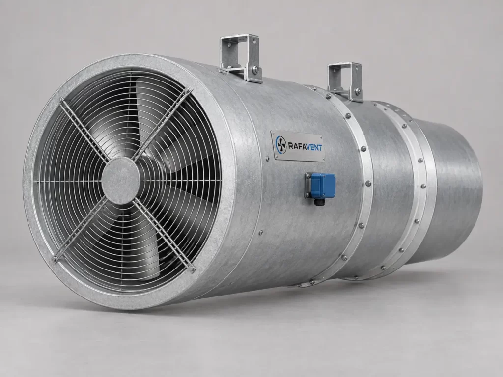
Longitudinal tunnel-ventilation fans engineered around required jet thrust, air velocity, tunnel geometry and operating strategy. RAFAVENT tunnel jet-fan construction is available from Ø560 to a maximum family size of Ø1400.
Selection basis
Primary duty
Required installed thrust in newtons, traffic direction, tunnel cross-section, spacing and permissible air velocity.
Installation losses
Ceiling clearance, wall proximity, silencers, mounting cradle, obstructions and cross-flow can reduce effective installed thrust.
Operating mode
Unidirectional or reversible airflow, normal ventilation, emergency strategy, VFD control and redundancy philosophy.
Preliminary model selection
Nominal thrust is calculated from air momentum at standard-density air (approximately 1.2 kg/m³). Use installed-thrust correction factors during detailed design.
| Model | Impeller | Nominal airflow (m³/h) | Outlet velocity (m/s) | Nominal thrust (N) | Preliminary motor selection (kW) | Speed (rpm) | Acoustic data status |
|---|---|---|---|---|---|---|---|
| TJF-560 | Ø560 | 20,000 | 22.6 | 151 | 5.5 | 1450 | Test data required |
| TJF-630 | Ø630 | 28,000 | 24.9 | 232 | 7.5 | 1450 | Test data required |
| TJF-710 | Ø710 | 40,000 | 28.0 | 373 | 11 | 1450 | Test data required |
| TJF-800 | Ø800 | 55,000 | 30.4 | 557 | 18.5 | 1450 | Test data required |
| TJF-900 | Ø900 | 72,000 | 31.4 | 754 | 22 | 980 | Test data required |
| TJF-1000 | Ø1000 | 90,000 | 31.8 | 954 | 30 | 980 | Test data required |
| TJF-1120 | Ø1120 | 110,000 | 31.0 | 1,137 | 37 | 980 | Test data required |
| TJF-1250 | Ø1250 | 135,000 | 30.6 | 1,377 | 55 | 980 | Test data required |
| TJF-1400 | Ø1400 | 160,000 | 28.9 | 1,540 | 75–110 | 740–1200 | Test data required |
Acoustic performance for this configuration is not verified for acoustic selection. Specify LwA or LpA, frequency bands, duty point, sound path and test method; LpA also requires measurement distance and environment. A fixed ±6 dB uncertainty without supporting analysis and test documentation is not a verified uncertainty.
Calculated performance curves
These tables are theoretical speed-change scenarios for fixed geometry and density, not measured Q–Ps or Q–Pt curves. For speed ratio r = n/n_ref, airflow scales with r and ideal thrust with r². The theoretical shaft-power ratio P/P_ref is r³. P_ref must be the measured or calculated absorbed shaft power at the reference duty; it is not the nominal motor rating. No absolute shaft-power value is stated because that reference power is not documented for these generic scenarios. System duty and installation losses require separate assessment.
TJF-560 — calculated speed/thrust curve
| Speed setting | Airflow (m³/h) | Nominal thrust (N) | Shaft power ratio P/P_ref |
|---|---|---|---|
| 0% | 0 | 0 | 0.000 |
| 25% | 5,000 | 9 | 0.016 |
| 50% | 10,000 | 38 | 0.125 |
| 75% | 15,000 | 85 | 0.422 |
| 90% | 18,000 | 122 | 0.729 |
| 100% | 20,000 | 151 | 1.000 |
TJF-630 — calculated speed/thrust curve
| Speed setting | Airflow (m³/h) | Nominal thrust (N) | Shaft power ratio P/P_ref |
|---|---|---|---|
| 0% | 0 | 0 | 0.000 |
| 25% | 7,000 | 15 | 0.016 |
| 50% | 14,000 | 58 | 0.125 |
| 75% | 21,000 | 131 | 0.422 |
| 90% | 25,200 | 188 | 0.729 |
| 100% | 28,000 | 232 | 1.000 |
TJF-710 — calculated speed/thrust curve
| Speed setting | Airflow (m³/h) | Nominal thrust (N) | Shaft power ratio P/P_ref |
|---|---|---|---|
| 0% | 0 | 0 | 0.000 |
| 25% | 10,000 | 23 | 0.016 |
| 50% | 20,000 | 93 | 0.125 |
| 75% | 30,000 | 210 | 0.422 |
| 90% | 36,000 | 302 | 0.729 |
| 100% | 40,000 | 373 | 1.000 |
TJF-800 — calculated speed/thrust curve
| Speed setting | Airflow (m³/h) | Nominal thrust (N) | Shaft power ratio P/P_ref |
|---|---|---|---|
| 0% | 0 | 0 | 0.000 |
| 25% | 13,750 | 35 | 0.016 |
| 50% | 27,500 | 139 | 0.125 |
| 75% | 41,250 | 313 | 0.422 |
| 90% | 49,500 | 451 | 0.729 |
| 100% | 55,000 | 557 | 1.000 |
TJF-900 — calculated speed/thrust curve
| Speed setting | Airflow (m³/h) | Nominal thrust (N) | Shaft power ratio P/P_ref |
|---|---|---|---|
| 0% | 0 | 0 | 0.000 |
| 25% | 18,000 | 47 | 0.016 |
| 50% | 36,000 | 189 | 0.125 |
| 75% | 54,000 | 424 | 0.422 |
| 90% | 64,800 | 611 | 0.729 |
| 100% | 72,000 | 754 | 1.000 |
TJF-1000 — calculated speed/thrust curve
| Speed setting | Airflow (m³/h) | Nominal thrust (N) | Shaft power ratio P/P_ref |
|---|---|---|---|
| 0% | 0 | 0 | 0.000 |
| 25% | 22,500 | 60 | 0.016 |
| 50% | 45,000 | 239 | 0.125 |
| 75% | 67,500 | 537 | 0.422 |
| 90% | 81,000 | 773 | 0.729 |
| 100% | 90,000 | 954 | 1.000 |
TJF-1120 — calculated speed/thrust curve
| Speed setting | Airflow (m³/h) | Nominal thrust (N) | Shaft power ratio P/P_ref |
|---|---|---|---|
| 0% | 0 | 0 | 0.000 |
| 25% | 27,500 | 71 | 0.016 |
| 50% | 55,000 | 284 | 0.125 |
| 75% | 82,500 | 640 | 0.422 |
| 90% | 99,000 | 921 | 0.729 |
| 100% | 110,000 | 1,137 | 1.000 |
TJF-1250 — calculated speed/thrust curve
| Speed setting | Airflow (m³/h) | Nominal thrust (N) | Shaft power ratio P/P_ref |
|---|---|---|---|
| 0% | 0 | 0 | 0.000 |
| 25% | 33,750 | 86 | 0.016 |
| 50% | 67,500 | 344 | 0.125 |
| 75% | 101,250 | 775 | 0.422 |
| 90% | 121,500 | 1,115 | 0.729 |
| 100% | 135,000 | 1,377 | 1.000 |
TJF-1400 — calculated speed/thrust curve
| Speed setting | Airflow (m³/h) | Nominal thrust (N) | Shaft power ratio P/P_ref |
|---|---|---|---|
| 0% | 0 | 0 | 0.000 |
| 25% | 40,000 | 96 | 0.016 |
| 50% | 80,000 | 385 | 0.125 |
| 75% | 120,000 | 866 | 0.422 |
| 90% | 144,000 | 1,247 | 0.729 |
| 100% | 160,000 | 1,540 | 1.000 |
AF1400 project reference — construction and performance basis
The AF1400 project reference is distinct from the generic TJF-1400 free-jet scenarios above. Construction details and calculated reference duties must be kept separate from the tested performance of the final fan, guide vanes and silencers.
| Parameter | Basis and status |
|---|---|
| Impeller diameter | 1400 mm project reference. |
| Design speed | 1200 rpm reference with VFD; the motor nameplate speed does not establish the permitted impeller operating speed. |
| Motor rating | 110 kW nominal motor rating; not absorbed shaft power or a measured performance result. |
| Airflow and pressure | R4 calculated values are not a tested duty for the final assembly. No verified static-pressure rating for the final configuration is stated here. |
| Configuration revision | The R4 calculation basis and R5.8 guide-vane arrangement are different. Results must not be transferred directly to the final configuration with guide vanes and silencers. |
| Final assembly evidence | Performance, thrust, sound and any requested temperature or conformity rating require the relevant model-specific documents and test report. |
Pressure basis clarification: the earlier approximate 1270 Pa entry must not be used as a static-pressure rating for the final assembly. The Iranian AF1400 reference identifies the R4 pressure as calculated total pressure (Pt), distinguishes it from static pressure (Ps), and explains the revision limits. Obtain the controlled engineering documents for project selection.
Construction and installation options
- Rolled, flanged heavy-gauge steel casing
- Project-specific corrosion-protection coating
- Aerodynamic impeller with adjustable design pitch
- External terminal box and protected cable routing
- Inlet and outlet attenuators sized to the duty
- Mounting cradle, feet or ceiling suspension arrangement
- Anti-vibration mounts and flexible connections where required
- Protective guards and inspection access
- Reversible impeller/motor arrangement where specified
- VFD suitability subject to motor and cable selection
Installed-thrust engineering checks
Geometry
Confirm tunnel area, hydraulic diameter, fan spacing, mounting elevation and clearance from soffit and walls.
Aerodynamics
Apply corrections for silencers, inlet distortion, cross-wind, traffic blockage and interaction between adjacent fans.
Electrical & controls
Confirm start method, VFD range, emergency sequence, motor protection, IP class and project power supply.
Information required for final selection
Provide required installed thrust, tunnel dimensions, ambient and emergency temperatures, reversible duty, permissible sound level, available electrical supply, control philosophy, mounting limits, coating environment and applicable project certification requirements.
Technical documents, dimensions and service
Technical documents and dimensions
Final dimensions, mounting details, silencer arrangement, materials, motor data and project drawings are issued for the selected tunnel and duty after engineering review.
Installation and maintenance
Confirm structural supports, installation clearances, access, cable routing, guards, vibration control and the approved project-specific O&M requirements.
Selection tables and calculated thrust curves are preliminary engineering guidance, not certified RAFAVENT test ratings or F300/F400 evidence. Confirm the installed thrust, operating duty and controlled documents before order.
Request an engineering selection
Send the duty point, installation arrangement, operating conditions and available drawings for a project-specific selection.
Send project requirements